18
|
Configuration
Installer and user reference guide
104
R R8T7V1B
VRV IV heat pump for indoor installation
4P499898-1B – 2021.12
#
Action
Button/display
3
Select setting 5.
("X×" depends on the setting that
you want to select.)
BS2 [X×]
(= binary 5)
4
Display the value of setting 5.
(there are 8 units connected)
BS3 [1×]
(= binary 8)
5
Quit mode 1.
BS1 [1×]
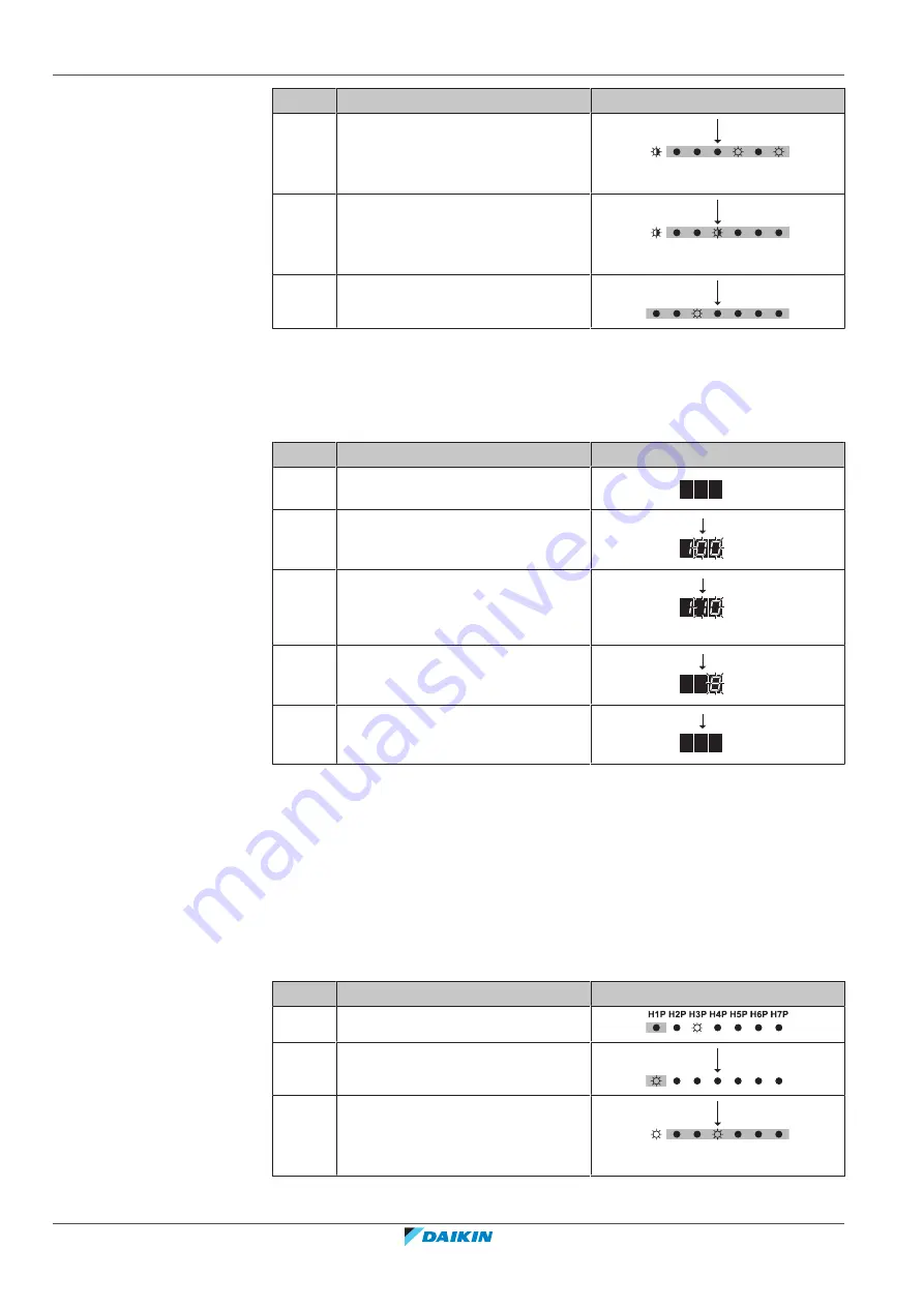
Example: 7‑segments display – Mode 1
(in case of 8 HP)
You can read out setting [1‑10] (= the total number of connected units (heat
exchanger unit + indoor units)) as follows:
#
Action
Button/display
1
Start from the default situation.
2
Select mode 1.
BS1 [1×]
3
Select setting 10.
("X×" depends on the setting that
you want to select.)
BS2 [X×]
4
Display the value of setting 10.
(there are 8 units connected)
BS3 [1×]
5
Quit mode 1.
BS1 [1×]
18.2.6 To use mode 2
In mode 2 you can make field settings to configure the system. How to do this
differs slightly depending on the model.
Example: 7‑LEDs display – Mode 2
(in case of 5 HP)
You can change the value of setting [2‑8] (= T
e
target temperature during cooling
operation) to 4 (= 8°C) as follows:
#
Action
Button/display
1
Start from the default situation.
2
Select mode 2.
BS1 [5 s]
3
Select setting 8.
("X×" depends on the setting that
you want to select.)
BS2 [X×]
(= binary 8)


