background image

44

REYQ-TAYCA

EDUS371706C-D

REYQ96TAYCA

4D107380A

Summary of Contents for VRV IV REYQ-TAYCA

Page 1: ...EDUS371706C D 202002 Engineering Data Heat Recovery 60 Hz Design Manual REYQ TAYCA 575 V ...

Page 2: ......

Page 3: ...ty 16 8 Capacity Range 17 8 1 Connection Ratio 17 8 2 Capacity Range of Connectable Indoor Units 18 8 3 Limitation of Capacity Index for Heat Recovery 19 9 Specifications 20 10 Dimensions 25 11 Service Space 28 12 Center of Gravity 30 13 Foundation Drawing 32 14 Piping Diagrams 33 15 Wiring Diagrams 35 16 Field Wiring 37 17 Electrical Characteristics 40 18 Operation Limits 41 19 Low Ambient Coolin...

Page 4: ...66 25 Safety Devices Setting 68 25 1 FXFQ T 68 25 2 FXZQ TA 68 25 3 FXUQ P 68 25 4 FXEQ P 68 25 5 FXDQ M 69 25 6 FXSQ TA 69 25 7 FXMQ PB 69 25 8 FXMQ M 69 25 9 FXHQ M 70 25 10 FXAQ P 70 25 11 FXLQ M FXNQ M 70 25 12 FXTQ TA 70 Appendix 71 1 Introduction 72 1 1 ED Book List 72 1 2 Publication List of Engineering Data for VRV Products 73 ...

Page 5: ...lows installation without additional drain pan heater Added peace of mind with ability of Auto changeover to back up auxiliary heat Variable Refrigerant Temperature VRT technology delivers year round comfort and efficiencies Designed and optimized for Total Cost of Construction TCC and overall Life Cycle Cost LCC Long pipe lengths with up to 295 ft allowable height difference between outdoor and i...

Page 6: ...Q96TAYCU REYQ120TAYCA REYQ120TAYCU REYQ144TAYCA REYQ144TAYCU REYQ168TAYCA REYQ168TAYCU REYQ192TAYCA REYQ192TAYCU REYQ216TAYCA REYQ216TAYCU REYQ240TAYCA REYQ240TAYCU REYQ264TAYCA REYQ264TAYCU REYQ288TAYCA REYQ288TAYCU REYQ312TAYCA REYQ312TAYCU REYQ336TAYCA REYQ336TAYCU REYQ360TAYCA REYQ360TAYCU REYQ384TAYCA REYQ384TAYCU ...

Page 7: ...t 384 REY Q T A A YC Minor Revision Power Supply Symbol YC 3 phase 575 V 60 Hz Indicates Minor Change Category Indicates Major Design Category Capacity Indication in Cooling Refrigerant Q R410A Unit category REY Outdoor unit air cooled heat recovery type ...

Page 8: ...tu h 60 60 000 Btu h 12 12 000 Btu h 36 36 000 Btu h 72 72 000 Btu h 15 15 000 Btu h 42 42 000 Btu h 96 96 000 Btu h Refrigerant Q R410A Shape F Ceiling mounted cassette Round flow with sensing Z VISTA 2 2 cassette unit U 4 way blow ceiling suspended E One way blow cassette D Slim ceiling mounted duct S MSP concealed ducted unit M Ceiling mounted duct H Ceiling suspended A Wall mounted L Floor sta...

Page 9: ...nit BS T VJ Q 36 Single Branch Selector unit only necessary for Heat Recovery System Power supply symbol VJ 1 phase 208 230 V 60 Hz Indicates major design category Capacity indication of connectable indoor units per branch Refrigerant R410A Number of branches 4 4 branches 6 6 branches 8 8 branches 10 10 branches 12 12 branches Unit category BS Branch Selector unit BS T VJ Q 12 54 Multi Branch Sele...

Page 10: ... Btu h 72 72 000 Btu h 96 96 000 Btu h Refrigerant Q R410A Shape M Ceiling mounted duct Series category X Inverter Unit category F Indoor unit for air cooled type Outdoor Air Processing Unit U G 300 V A M VJ Standard symbol U United States of America Power supply symbol VJ 1 phase 208 230 V 60 Hz Indicates major design category Airflow rate H 300 300 cfm 600 600 cfm 470 470 cfm 1200 1 200 cfm Moun...

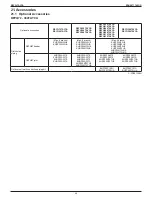
Page 11: ...evision Heat Recovery 575 V Model name REYQ72TAYCA REYQ96TAYCA REYQ120TAYCA REYQ144TAYCA REYQ168TAYCA Outdoor unit 1 REYQ72TAYCA REYQ96TAYCA REYQ120TAYCA REYQ144TAYCA REYQ168TAYCA Model name REYQ192TAYCA REYQ216TAYCA REYQ240TAYCA REYQ264TAYCA Outdoor unit 1 REYQ96TAYCA REYQ96TAYCA REYQ120TAYCA REYQ120TAYCA Outdoor unit 2 REYQ96TAYCA REYQ120TAYCA REYQ120TAYCA REYQ144TAYCA Model name REYQ288TAYCA RE...

Page 12: ...ype FXEQ 07P 09P 12P 15P 18P 24P Slim ceiling mounted duct type FXDQ 07M 09M 12M 18M 24M MSP concealed ducted unit FXSQ 05TA 07TA 09TA 12TA 15TA 18TA 24TA 30TA 36TA 48TA 54TA Ceiling mounted duct type Middle and high static pressure FXMQ 07PB 09PB 12PB 15PB 18PB 24PB 30PB 36PB 48PB 54PB Ceiling mounted duct type FXMQ 72M 96M Ceiling suspended type FXHQ 12M 24M 36M Wall mounted type FXAQ 07P 09P 12...

Page 13: ...eries Model Name Power Supply Standard Heat Recovery BS 4Q54T 6Q54T 8Q54T 10Q54T 12Q54T VJ Note No interchangeability between BSV Q36PVJU and BS Q54TVJ VJ 1 phase 208 230 V 60 Hz 4 4 Air Treatment Equipment Outdoor Air Processing Unit Series Model Name Power Supply Standard FXMQ 48MF 72MF 96MF VJU VJ 1 phase 208 230 V 60 Hz U VJU Standard symbol Energy Recovery Ventilator VAM series Series Model N...

Page 14: ...or Units REYQ72TAYCA REYQ96TAYCA REYQ120TAYCA REYQ144TAYCA REYQ168TAYCA 6 8 10 12 14 ton Double Outdoor Units REYQ192TAYCA REYQ288TAYCA REYQ216TAYCA REYQ312TAYCA REYQ240TAYCA REYQ336TAYCA REYQ264TAYCA 16 18 20 22 24 26 28 ton Triple Outdoor Units REYQ360TAYCA REYQ384TAYCA 30 32 ton ...

Page 15: ...n with BYFQ60C3W1W Shown with BYFQ60C3W1S Ceiling suspended type FXHQ M 4 way blow ceiling suspended type FXUQ P Wall mounted type FXAQ P One way blow cassette type FXEQ P Floor standing type FXLQ M Slim ceiling mounted duct type FXDQ M Concealed floor standing type FXNQ M MSP concealed ducted unit FXSQ TA Air handling unit FXTQ TA Ceiling mounted duct type Middle and high static pressure FXMQ PB ...

Page 16: ...EDUS371706C D 5 3 Branch Selector Unit Single branch selector unit BSQ T Multi branch selector unit BS Q54T 5 4 Air Treatment Equipment Outdoor air processing unit FXMQ MF Energy recovery ventilator VAM series VAM G ...

Page 17: ...0 42 2 1 l REYQ168TAYCA 14 17 5 49 2 1 l REYQ192TAYCA 16 20 0 56 3 2 ll BHFP26P100U BHFP26P100UA REYQ216TAYCA 18 22 5 63 3 2 l l REYQ240TAYCA 20 25 0 70 3 2 ll REYQ264TAYCA 22 27 5 77 4 2 l l REYQ288TAYCA 24 30 0 84 4 2 ll REYQ312TAYCA 26 32 5 91 4 2 l l REYQ336TAYCA 28 35 0 98 5 2 ll REYQ360TAYCA 30 37 5 105 5 3 lll BHFP26P151U BHFP26P151UA REYQ384TAYCA 32 40 0 112 5 3 ll l Note 1 For multiple co...

Page 18: ...r unit Single Branch Selector unit Multi Branch Selector unit Single Branch Selector unit Multi Branch Selector unit BSQ36TVJ BSQ60TVJ BSQ96TVJ BS4Q54TVJ BS6Q54TVJ BS8Q54TVJ BS10Q54TVJ BS12Q54TVJ BSVQ36PVJU BSVQ60PVJU BSVQ96PVJU BSV4Q36PVJU BSV6Q36PVJU Heat Recovery REYQ TA REYQ TAYCA Connectable Connectable Not connectable Not connectable ...

Page 19: ...130 1 In heating mode fan speed is limited to L tap when indoor units capacity 130 2 Fan speed follows the setting of the remote controllers not limited by indoor units connection capacity 3 Fan speed is limited to L tap when outdoor air temperature goes down to below 85 1 F 29 5 C and indoor air temperature is in condition A 1 It returns to remote controller setting when outdoor air temperature g...

Page 20: ... 84 to 218 336 29 Double outdoor units 16 192 REYQ192TAYCA 96 to 249 307 33 18 216 REYQ216TAYCA 108 to 280 345 37 20 240 REYQ240TAYCA 120 to 312 384 41 22 264 REYQ264TAYCA 132 to 343 422 45 24 288 REYQ288TAYCA 144 to 374 460 49 26 312 REYQ312TAYCA 156 to 405 499 54 28 336 REYQ336TAYCA 168 to 436 537 58 Triple outdoor units 30 360 REYQ360TAYCA 180 to 468 468 62 32 384 REYQ384TAYCA 192 to 499 499 64...

Page 21: ...90 or less 290 or less 290 or less Maximum capacity index of connectable indoor units per branch 1 54 or less 54 or less 54 or less 54 or less 54 or less Note 1 When the total capacity of indoor units to be connected downstream is larger than 54 Max 96 use a junction pipe kit KHRP26A250T optional parts to join two connections downstream from the Branch Selector unit High and low pressure gas pipin...

Page 22: ...9 1 C1220T Brazing connection f7 8 22 2 C1220T Brazing connection f1 1 8 28 6 C1220T Brazing connection High Low pressure gas pipe in mm f5 8 15 9 C1220T Brazing Connection f3 4 19 1 C1220T Brazing Connection f3 4 19 1 C1220T Brazing Connection Weight lbs kg 727 330 727 330 727 330 Sound pressure level Reference data dB A 65 65 65 Sound power level Reference data dB 79 80 80 5 Safety devices High ...

Page 23: ... C1220T Brazing connection Suction gas pipe in mm f1 1 8 28 6 C1220T Brazing connection f1 1 8 28 6 C1220T Brazing connection f1 1 8 28 6 C1220T Brazing connection High Low pressure gas pipe in mm f7 8 22 2 C1220T Brazing Connection f7 8 22 2 C1220T Brazing Connection f1 1 8 28 6 C1220T Brazing Connection Weight lbs kg 793 360 793 360 727 727 330 330 Sound pressure level Reference data dB A 66 66 ...

Page 24: ...5 9 C1220T Brazing connection f5 8 15 9 C1220T Brazing connection f3 4 19 1 C1220T Brazing connection Suction gas pipe in mm f1 1 8 28 6 C1220T Brazing connection f1 3 8 34 9 C1220T Brazing connection f1 3 8 34 9 C1220T Brazing connection High Low pressure gas pipe in mm f1 1 8 28 6 C1220T Brazing Connection f1 1 8 28 6 C1220T Brazing Connection f1 1 8 28 6 C1220T Brazing Connection Weight lbs kg ...

Page 25: ...19 1 C1220T Brazing connection f3 4 19 1 C1220T Brazing connection f3 4 19 1 C1220T Brazing connection Suction gas pipe in mm f1 3 8 34 9 C1220T Brazing connection f1 3 8 34 9 C1220T Brazing connection f1 3 8 34 9 C1220T Brazing connection High Low pressure gas pipe in mm f1 1 8 28 6 C1220T Brazing Connection f1 1 8 28 6 C1220T Brazing Connection f1 1 8 28 6 C1220T Brazing Connection Weight lbs kg...

Page 26: ...6 226 268 Drive Direct drive Direct drive Connecting pipes Liquid pipe in mm f3 4 19 1 C1220T Brazing connection f3 4 19 1 C1220T Brazing connection Suction gas pipe in mm f1 5 8 41 3 C1220T Brazing connection f1 5 8 41 3 C1220T Brazing connection High Low pressure gas pipe in mm f1 3 8 34 9 C1220T Brazing Connection f1 3 8 34 9 C1220T Brazing Connection Weight lbs kg 727 727 727 330 330 330 727 7...

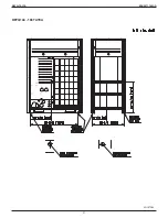
Page 27: ...25 REYQ TAYCA EDUS371706C D 10 Dimensions REYQ72 168TAYCA C 3D107340A ...

Page 28: ...ve wall heights are exceeded then h2 2 and h1 2 should be added to the front and suction side service spaces respectively as shown in the following figure 3 When installing the units the most appropriate pattern should be selected from Installation and repair space drawing in order to obtain the best fit in the space available always bearing in mind the need to leave enough room for a person to pa...

Page 29: ...ve wall heights are exceeded then h2 2 and h1 2 should be added to the front and suction side service spaces respectively as shown in the following figure 3 When installing the units the most appropriate pattern should be selected from Installation and repair space drawing in order to obtain the best fit in the space available always bearing in mind the need to leave enough room for a person to pa...

Page 30: ...it side 2 If the above wall heights are exceeded then h2 2 and h1 2 should be added to the front and suction side service spaces respectively as shown in the following figure 3 When installing the units the most appropriate pattern should be selected from Installation and repair space drawing in order to obtain the best fit in the space available always bearing in mind the need to leave enough roo...

Page 31: ...hts are exceeded then h2 2 and h1 2 should be added to the front and suction side service spaces respectively as shown in the following figure 3 When installing the units the most appropriate pattern should be selected from Installation and repair space drawing in order to obtain the best fit in the space available always bearing in mind the need to leave enough room for a person to pass between u...

Page 32: ...30 REYQ TAYCA EDUS371706C D 12 Center of Gravity REYQ72 120TAYCA 4D107384 ...

Page 33: ...31 REYQ TAYCA EDUS371706C D REYQ144 168TAYCA 4D107385 ...

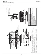
Page 34: ...surface shall be finished with mortar The corner edges shall be chamfered 3 When the foundation is built on a concrete floor rubble is not necessary However the surface of the section on which the foundation is built shall have rough finish 4 A drain ditch shall be made around the foundation to thoroughly drain water from the equipment installation area 5 When installing the equipment on a roof th...

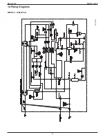
Page 35: ...33 REYQ TAYCA EDUS371706C D 14 Piping Diagrams REYQ72 120TAYCA 3D107166 ...

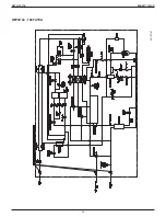
Page 36: ...34 REYQ TAYCA EDUS371706C D REYQ144 168TAYCA 3D107167 ...

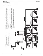
Page 37: ...FER TO THE INSTALLATION MANUAL OF THE OPTIONAL ADAPTOR 4 FOR CONNECTION WIRING TO INDOOR OUTDOOR TRANSMISSION F1 F2 OUTDOOR OUTDOOR TRANSMISSION F1 F2 OUTDOOR MULTI TRANSMISSION Q1 Q2 REFER TO THE INSTALLATION MANUAL 5 HOW TO USE BS1 3 SWITCH REFER TO SERVICE PRECAUTION LABEL ON CONTROL BOX COVER 6 WHEN OPERATING DO NOT SHORTCIRCUIT THE PROTECTION DEVICE S1PH 7 COLORS BLK BLACK RED RED BLU BLUE WH...

Page 38: ...C A1P Y1E ELECTRIC EXPANSION VALVE HEAT EXC UPPER K8R MAGNETIC RELAY Y7S A1P Y2E ELECTRIC EXPANSION VALVE SUBCOOL HEAT EXC K9R MAGNETIC RELAY Y4S A1P K11R MAGNETIC RELAY Y3S A1P Y3E ELECTRIC EXPANSION VALVE HEAT EXC LOWER K12R MAGNETIC RELAY Y5S A1P Y4E ELECTRIC EXPANSION VALVE INJECTION K13R MAGNETIC RELAY Y6S A1P Y5E ELECTRIC EXPANSION VALVE REFRIGERANT COOLING L1R REACTOR Y6E ELECTRIC EXPANSION...

Page 39: ...ng shown are general points of connection guides only and are not intended for or to include all details for a specific installation 7 Be sure to install the switch and the fuse breaker to the power line of each piece of equipment 8 Install the main switch that can interrupt all the power sources in an integrated manner because this system consists of the equipment utilizing the multiple power sou...

Page 40: ... are general points of connection guides only and are not intended for or to include all details for a specific installation 7 Be sure to install the switch and the fuse breaker to the power line of each piece of equipment 8 Install the main switch that can interrupt all the power sources in an integrated manner because this system consists of the equipment utilizing the multiple power sources 9 I...

Page 41: ... are general points of connection guides only and are not intended for or to include all details for a specific installation 7 Be sure to install the switch and the fuse breaker to the power line of each piece of equipment 8 Install the main switch that can interrupt all the power sources in an integrated manner because this system consists of the equipment utilizing the multiple power sources 9 I...

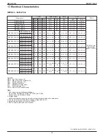
Page 42: ...3 22 3 30 30 15 7 15 7 0 7 2 2 1 0 2 2 REYQ144TAYCA REYQ312TAYCA REYQ144TAYCA 60 575 518 632 22 3 24 9 30 30 16 8 16 8 0 7 2 2 1 0 2 2 REYQ168TAYCA REYQ336TAYCA REYQ168TAYCA 60 575 518 632 24 9 24 9 30 30 18 1 18 1 0 7 2 2 1 0 2 2 REYQ168TAYCA REYQ360TAYCA REYQ120TAYCA 60 575 518 632 18 2 18 2 18 2 25 25 25 11 8 11 8 11 8 0 7 2 3 1 0 2 3 REYQ120TAYCA REYQ120TAYCA REYQ384TAYCA REYQ120TAYCA 60 575 5...

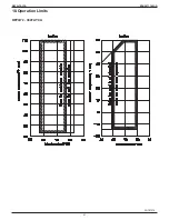
Page 43: ...41 REYQ TAYCA EDUS371706C D 18 Operation Limits REYQ72 384TAYCA 3D107375 ...

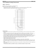
Page 44: ...without the low ambient cooling function Function is engaged by a field setting on the outdoor unit to enable Low Ambient Cooling and a dip switch setting is necessary on the Single Branch Selector Boxes BSQ T series serving the indoor units NOT subject to Low Ambient Cooling requirements During operation below 23ºFDB 5ºCDB the available cooling capacity decreases as follows 14ºFDB 10ºCDB Reduces ...

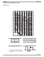
Page 45: ...43 REYQ TAYCA EDUS371706C D 20 Sound Levels Reference Data REYQ72TAYCA 4D107379B ...

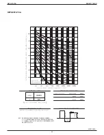
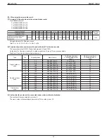
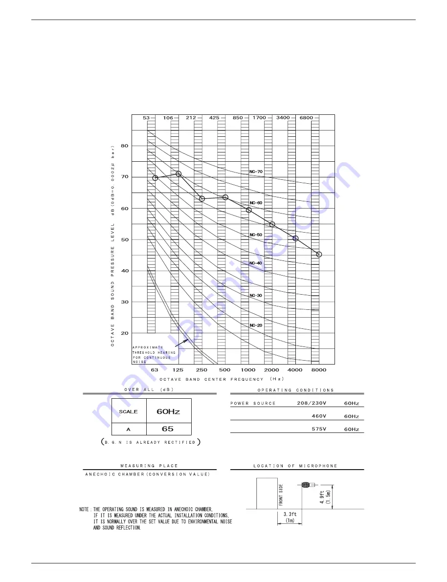
Page 46: ...44 REYQ TAYCA EDUS371706C D REYQ96TAYCA 4D107380A ...

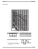
Page 47: ...45 REYQ TAYCA EDUS371706C D REYQ120TAYCA 4D107381A ...

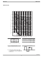
Page 48: ...46 REYQ TAYCA EDUS371706C D REYQ144TAYCA 4D107382A ...

Page 49: ...47 REYQ TAYCA EDUS371706C D REYQ168TAYCA 4D107383A ...

Page 50: ...Max 8 branch KHRP25M33H9 KHRP25M33HA Max 8 branch KHRP25M33H9 KHRP25M33HA KHRP25M72H9 KHRP25M72HA Max 8 branch KHRP25M33H9 KHRP25M33HA KHRP25M72H9 KHRP25M72HA KHRP25M73HU9 KHRP25M73HUA REFNET joint KHRP25A22T9 KHRP25A22TA KHRP25A33T9 KHRP25A33TA KHRP25A22T9 KHRP25A22TA KHRP25A33T9 KHRP25A33TA KHRP25M72TU9 KHRP25M72TUA KHRP25A22T9 KHRP25A33T9 KHRP25M72TU9 KHRP25M73TU9 KHRP25A22TA KHRP25A33TA KHRP25...

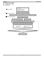
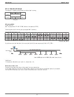
Page 51: ...the peak load of each room Define required total heat load to outdoor unit Indoor unit capacity corrected for indoor air temperature WB Required heat load Safety factor for the indoor units Yes No Piping length level difference Piping heat loss Safety factor for the outdoor unit Defrost only for heating capacity Outdoor air temperature Indoor air temperature Connection ratio Given Conditions Desig...

Page 52: ...7 157 1 14 00 30 7 32 2 16 8 16 8 24 9 23 4 14 2 14 2 173 2 16 00 36 1 36 4 13 3 13 3 21 5 21 2 13 0 13 0 167 8 Total heat load MBH From the above heat load calculation the maximum heat load for the system system peak load is 173 2 MBH Level difference 120 ft Select VRV indoor units FXMQ PB series for each room Equivalent pipe length 200 ft Safety factor In this example safety factor is not used i...

Page 53: ...al capacity MBH SHC Sensible heat capacity MBH Selection results of indoor units Room A Room B Room C Room D Room E Room F Room G Room H Max heat load MBH 36 1 36 4 17 3 17 3 30 9 30 8 14 2 14 2 Selected IDU FXMQ48PBVJU FXMQ48PBVJU FXMQ18PBVJU FXMQ18PBVJU FXMQ36PBVJU FXMQ36PBVJU FXMQ15PBVJU FXMQ15PBVJU Corrected TC MBH 48 0 48 0 18 0 18 0 36 0 36 0 14 2 14 2 In case of selection based on Total Hea...

Page 54: ...dex of connectable indoor units 1 Maximum number of connectable indoor units Single outdoor units 6 72 REYQ72TAYCA 51 to 93 144 12 8 96 REYQ96TAYCA 48 to 124 192 16 10 120 REYQ120TAYCA 60 to 156 240 20 12 144 REYQ144TAYCA 72 to 187 288 25 14 168 REYQ168TAYCA 84 to 218 336 29 Double outdoor units 16 192 REYQ192TAYCA 96 to 249 307 33 18 216 REYQ216TAYCA 108 to 280 345 37 20 240 REYQ240TAYCA 120 to 3...

Page 55: ... 188 12 8 197 13 4 203 13 5 209 13 7 210 13 7 210 13 7 99 146 9 57 188 13 8 194 13 9 199 14 1 202 14 1 202 14 1 202 14 1 103 146 10 2 184 14 3 190 14 4 193 14 5 193 14 5 193 14 5 193 14 5 106 146 10 9 182 14 9 187 15 0 187 15 0 187 15 0 187 15 0 187 15 0 110 146 11 9 178 15 7 178 15 7 178 15 7 178 15 7 178 15 7 178 15 7 115 146 13 3 154 15 9 154 15 9 155 15 9 155 15 9 155 15 9 155 15 9 118 133 13 ...

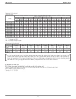
Page 56: ...st correction factor for heating capacity Therefore C 201 8 0 924 1 161 160 6 MBH If the corrected capacity C is the same or greater than the required total heat load A selection is complete If C A return to Procedure 3 2 and provisionally select a larger outdoor unit In this example 160 6 MBH C 173 2 MBH A so need to select a larger outdoor unit The capacity of REYQ216TAYCA at the same condition ...

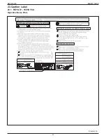
Page 57: ...55 REYQ TAYCA EDUS371706C D 23 Caution Label 23 1 REYQ72 168TAYCA Operation Name Plate 3P558142 1B ...

Page 58: ...56 REYQ TAYCA EDUS371706C D 3P558142 1B ...

Page 59: ...57 REYQ TAYCA EDUS371706C D 1P385984 1A ...

Page 60: ...58 REYQ TAYCA EDUS371706C D 1P385984 1A ...

Page 61: ...59 REYQ TAYCA EDUS371706C D 1P385984 1A ...

Page 62: ...60 REYQ TAYCA EDUS371706C D 1P385984 1A ...

Page 63: ...61 REYQ TAYCA EDUS371706C D 1P385984 1A ...

Page 64: ...62 REYQ TAYCA EDUS371706C D 1P385984 1A ...

Page 65: ...63 REYQ TAYCA EDUS371706C D Collective Indications Label 3P385987 1A ...

Page 66: ...64 REYQ TAYCA EDUS371706C D 3P385987 1A ...

Page 67: ...refrigerant gas is not exceeded in the unlikely event of major leak in the system and this in accordance to the local applicable regulations and standards Maximum concentration level The maximum charge of refrigerant and the calculation of the maximum concentration of refrigerant is directly related to the humanly occupied space in to which it could leak The unit of measurement of the concentratio...

Page 68: ...ty is divided into 2 entirely independent refrigerant systems then use the amount of refrigerant with which each separate system is charged Step 2 Calculate the smallest room volume ft 3 In case like the following calculate the volume of a b as a single room or as the smallest room a Where there are no smaller room divisions b Where there is a room division but there is an opening between the room...

Page 69: ...If the result of the above calculation exceeds the maximum concentration level then make similar calculations for the second then third smallest room and so until the result falls short of the maximum concentration Step 4 Dealing with the situations where the result exceeds the maximum concentration level Where the installation of a facility results in a concentration in excess of the maximum conc...

Page 70: ...oard fuse 250 V 3 15 A 250 V 3 15 A 250 V 3 15 A 250 V 3 15 A 250 V 3 15 A 250 V 3 15 A Fan motor thermal fuse F C Fan motor thermal protector F C Drain pump fuse F C C 4D110603 25 3 FXUQ P Model FXUQ18PVJU FXUQ24PVJU FXUQ30PVJU FXUQ36PVJU Printed circuit board fuse 250 V 3 15 A 250 V 3 15 A 250 V 3 15 A 250 V 3 15 A Drain pump thermal fuse F C Fan motor thermal protector F C Fan motor thermal fus...

Page 71: ...5 A Printed circuit board fuse Fan driver 250 V 6 3 A 250 V 6 3 A 250 V 6 3 A 250 V 6 3 A 250 V 6 3 A 250 V 6 3 A Drain pump thermal fuse F C 3D112398 25 7 FXMQ PB Model FXMQ07PBVJU FXMQ09PBVJU FXMQ12PBVJU FXMQ15PBVJU FXMQ18PBVJU Printed circuit board fuse 250 V 3 15 A 250 V 3 15 A 250 V 3 15 A 250 V 3 15 A 250 V 3 15 A Printed circuit board fuse Fan driver 250 V 5 A 250 V 5 A 250 V 5 A 250 V 6 3 ...

Page 72: ...48 120 or less OFF 275 18 135 10 ON 248 120 or less OFF 275 18 135 10 ON 248 120 or less OFF 275 18 135 10 ON 248 120 or less OFF 275 18 135 10 ON 248 120 or less C 3D045646B 25 12 FXTQ TA Model FXTQ09TAVJUA FXTQ12TAVJUA FXTQ18TAVJUA FXTQ24TAVJUA FXTQ30TAVJUA Model with factory disconnect FXTQ09TAVJUD FXTQ12TAVJUD FXTQ18TAVJUD FXTQ24TAVJUD FXTQ30TAVJUD Printed circuit board fuse F1U 32 V 3 A 32 V ...

Page 73: ...71 REYQ TAYCA EDUS371706C D Appendix 1 Introduction 72 1 1 ED Book List 72 1 2 Publication List of Engineering Data for VRV Products 73 ...

Page 74: ... Ceiling Mounted Duct Type FXDQ M EDUS39 600 F2 MSP Concealed Duct Unit FXSQ TA EDUS391777 F17 Ceiling Mounted Duct Type FXMQ PB EDUS391503A F4 Ceiling Mounted Duct Type FXMQ M EDUS39 900A F11 Ceiling Suspended Type FXHQ M EDUS39 600 F5 Wall Mounted Type FXAQ P EDUS391100 F6 Floor Standing Type Concealed Floor Standing Type FXLQ M FXNQ M EDUS391502 F7 Air Handling Unit FXTQ TA Engineering Data FXT...

Page 75: ... Design manual EDUS371706C D Capacity table EDUS371706C C H P 208 230 V 460 V RXYQ TATJA TAYDA USA Canada Design manual EDUS341703B D Jan 2020 Capacity table EDUS341703B C 575 V RXYQ TAYCA Canada Design manual EDUS341824A D Capacity table EDUS341824A C VRV Aurora H R 208 230 V 460 V 575 V RELQ TATJA TAYDA TAYCA USA Canada Design manual EDUS371705C D Feb 2020 Capacity table EDUS371705C C H P 208 23...

Page 76: ...AQ07 24PVJU USA EDUS391100 F6 Jan 2012 Floor Standing Type Concealed Floor Standing Type FXLQ07 24MVJU FXNQ07 24MVJU USA EDUS391502 F7 Jul 2015 Air Handling Unit FXTQ09 60TAVJUA FXTQ09 60TAVJUD USA Engineering Data FXTQ TA Sep 2016 Cased Coil Unit CXTQ24 60TASBLU USA Engineering Data CXTQ TA Outdoor Air Processing Unit FXMQ48 96MFVJU USA EDUS39 900A F10 May 2010 Single Branch Selector Unit BSQ36 9...

Page 77: ......

Page 78: ......

Page 79: ......

Page 80: ...or explosion Use only those parts and accessories supplied or specified by Daikin Ask a qualified installer or contractor to install those parts and accessories Use of unauthorised parts and accessories or improper installation of parts and accessories can result in water or refrigerant leakage electrical shock fire or explosion Read the user s manual carefully before using this product The user s...

Reviews: