background image

14 Piping installation

Installation and operation manual

26

RYYQ+RYMQ+RXYQ8~20U7Y1B

VRV IV+ heat pump

4P546220-1C – 2020.10

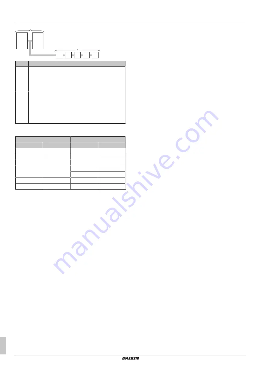
550

200

300

125

125

125 125 50

500

12 HP

8 HP

#

Action

1

Determine the connection ratio:

▪ Total outdoor unit capacity class = 500

▪ Total indoor unit capacity class = 550

=> CR≥100%

2

Determine parameter C:

▪ N=5

▪ 8 HP: N≥4 => C1=N×0.1=5×0.1 kg

▪ 12 HP: N<6 => C2=0 kg

=> C=C1+C2=0.5 kg

Metric piping.

 When using metric piping, replace the weight factors

in the formula by the ones from the following table:

Inch piping

Metric piping

Piping

Weight factor

Piping

Weight factor

Ø6.4 mm

0.022

Ø6 mm

0.018

Ø9.5 mm

0.059

Ø10 mm

0.065

Ø12.7 mm

0.12

Ø12 mm

0.097

Ø15.9 mm

0.18

Ø15 mm

0.16

Ø16 mm

0.18

Ø19.1 mm

0.26

Ø18 mm

0.24

Ø22.2 mm

0.37

Ø22 mm

0.35

Summary of Contents for VRV IV+

Page 1: ...ration manual VRV IV heat pump RYYQ8U7Y1B RYYQ10U7Y1B RYYQ12U7Y1B RYYQ14U7Y1B RYYQ16U7Y1B RYYQ18U7Y1B RYYQ20U7Y1B RYMQ8U7Y1B RYMQ10U7Y1B RYMQ12U7Y1B RYMQ14U7Y1B RYMQ16U7Y1B RYMQ18U7Y1B RYMQ20U7Y1B RXY...

Page 2: ...n Smjernice kako je izmijenjeno ir nyelv ek s m dos t saik rendelkez seit z p niejszymi poprawkami 18 19 20 21 22 23 24 25 Directivelor cu amendamentele respective Direktive z vsemi spremembami Direk...

Page 3: ...staava kyll stysl mp tila M C Kylm aine N Varmuuspainelaitteen asetus P bar Valmistusnumero ja valmistusvuosi katso mallin nimikilpi Maxim ln p pustn tlak PS K bar Minim ln maxim ln p pustn teplota TS...

Page 4: ...8 2 15 Symptom The display shows 88 14 8 2 16 Symptom The compressor in the outdoor unit does not stop after a short heating operation 14 8 2 17 Symptom The inside of an outdoor unit is warm even whe...

Page 5: ...ust read before installing Format Paper in the box of the outdoor unit Outdoor unit installation and operation manual Installation and operation instructions Format Paper in the box of the outdoor uni...

Page 6: ...e side Do NOT use taped wires stranded conductor wires extension cords or connections from a star system They can cause overheating electrical shock or fire Do NOT install a phase advancing capacitor...

Page 7: ...nsuring this product is disposed of correctly you will help to prevent potential negative consequences for the environment and human health For more information contact your installer or local authori...

Page 8: ...he point of leakage has been repaired or corrected before resuming operation WARNING Stop operation and shut off the power if anything unusual occurs burning smells etc Leaving the unit running under...

Page 9: ...cannot be made with a user interface whose display shows change over under centralised control refer to installation and operation manual of the user interface When the display change over under centr...

Page 10: ...ration if the room temperature is low 20 C 6 3 2 To use the dry program WITHOUT cool heat changeover remote control switch To start 1 Press the operation mode selector button on the user interface sev...

Page 11: ...the user interfaces as the master user interface The displays of slave user interfaces show change over under centralised control and slave user interfaces automatically follow the operation mode dire...

Page 12: ...F the power supply If the user interface display indicates the unit number the operation lamp flashes and the malfunction code appears Notify your installer and report the malfunction code If the syst...

Page 13: ...ndoor outdoor Abnormal user interface indoor communication Faulty wiring to outdoor outdoor Abnormal main sub user interface communication System mismatch Wrong type of indoor units combined Indoor un...

Page 14: ...hile the indoor unit is stopped When another indoor unit is in operation this noise is heard In order to prevent oil and refrigerant from remaining in the system a small amount of refrigerant is kept...

Page 15: ...9 TOTAL LENGTH OF LIQUID PIPE SIZE O6 4 x 0 022 105 CR 130 50 CR 105 50 CR 70 70 CR 85 85 CR 105 105 CR 130 8HP Total indoor unit capacity connection ratio CR 10 12HP 14 16HP 18 20HP 2 0 1 5 1 5 1 2 1...

Page 16: ...wireless dedicated depending on indoor unit type i Cool heat changeover remote control switch 13 Unit installation 13 1 Preparing the installation site 13 1 1 Installation site requirements of the ou...

Page 17: ...to prevent vibration and noise NOTICE When the installation height of the unit needs to be increased do NOT use stands to only support the corners Stands under the unit must be at least 100 mm wide 10...

Page 18: ...8 19 1 9 5 10 22 2 9 5 12 16 28 6 12 7 18 22 28 6 15 9 24 34 9 15 9 Outdoor unit capacity type HP Piping outer diameter size mm Gas pipe Liquid pipe 26 34 34 9 19 1 36 54 41 3 19 1 D Piping between r...

Page 19: ...pipe Liquid pipe 20 25 30 9 5 6 4 50 12 7 60 9 5 71 15 9 14 1 3 To select refrigerant branch kits Refrigerant refnets For piping example refer to To select the piping size 418 When using refnet joint...

Page 20: ...s to the outmost outdoor unit when the system stops NOT allowed oil remains in piping Allowed If the piping length between the outdoor units exceeds 2 m create a rise of 200 mm or more in the gas line...

Page 21: ...tion label a attached to the joint comes to the top Do not tilt the joint more than 7 5 see view A Do not install the joint vertically see view B a a A B 7 5 7 5 a Caution label NOT allowed Allowed Ma...

Page 22: ...the service port make sure to tighten the service port cover securely For the tightening torque refer to the table below Check for refrigerant leaks after tightening the service port cover Tightening...

Page 23: ...ait to apply setting 2 21 until the outdoor unit has finished the initialisation Leak test and vacuum drying Checking the refrigerant piping involves Checking for any leakages in the refrigerant pipin...

Page 24: ...proceed as follows 1 Evacuate the system for at least 2 hours to a target vacuum of 100 7 kPa 1 007 bar 5 Torr absolute 2 Check that with the vacuum pump turned off the target vacuum is maintained for...

Page 25: ...pre charge a portion of refrigerant through the liquid line before proceeding with the actual automatic or manual charging This step is included in below procedure see To charge refrigerant 428 It can...

Page 26: ...it capacity class 550 CR 100 2 Determine parameter C N 5 8 HP N 4 C1 N 0 1 5 0 1 kg 12 HP N 6 C2 0 kg C C1 C2 0 5 kg Metric piping When using metric piping replace the weight factors in the formula by...

Page 27: ...onal refrigerant amount via setting 2 14 Go to test run Step 4b Close valves D and B R Q R Q R Q Continued on next page p p R410A N2 C D A B Charging refrigerant Step 6 Proceed with automatic or manua...

Page 28: ...pear e 2 indoor temperature out of range and e 3 outdoor temperature out of range Push BS1 to leave program Charging is finished Fill in the amount on the additional refrigerant charge label Input the...

Page 29: ...charging port is connected to the piping inside the unit The unit s internal piping is already factory charged with refrigerant so be careful when connecting the charge hose After adding the refrigera...

Page 30: ...et Retry autocharge procedure Indoor unit is out of temperature range for leak detection operation Retry when ambient conditions are satisfied Outdoor unit is out of temperature range for leak detecti...

Page 31: ...19397 RYYQ40 RXYQ40 20378 RYYQ42 RXYQ42 20629 RYYQ44 RXYQ44 21132 RYYQ46 RXYQ46 21887 RYYQ48 RXYQ48 22641 RYYQ50 RXYQ50 23899 RYYQ52 RXYQ52 25157 RYYQ54 RXYQ54 26415 INFORMATION Multi units are standa...

Page 32: ...iring d Tie wrap a Knockout hole has to be removed Close the hole to avoid small animals or dirt from entering X1A c d a b a b 8 12 HP 14 20 HP Fix to the indicated plastic brackets using field suppli...

Page 33: ...pipes using finishing tape as shown in figure below a b c d e a Liquid pipe b Gas pipe c Insulator d Transmission wiring F1 F2 e Finishing tape 15 7 To route and fix the power supply NOTICE When rout...

Page 34: ...gs it is also possible to confirm the current operation parameters of the unit Push buttons and DIP switches Item Description Push buttons By operating the push buttons it is possible to Perform speci...

Page 35: ...r and to protect the compressor Turn on the power supply of the outdoor unit and all indoor units When the communication between indoor units and outdoor unit s is established and normal the 7 segment...

Page 36: ...ter position 1 6 The current Tc target parameter position 1 10 Shows the total number of connected indoor units 1 13 Shows the total number of connected outdoor units in case of multiple outdoor syste...

Page 37: ...leak detection function see 16 2 Using the leak detection function 438 2 20 Manual additional refrigerant charge 2 20 Description 0 default Deactivated 1 Activated To stop the manual additional refri...

Page 38: ...e as well Working on an indoor unit while performing a test operation is dangerous NOTICE Be sure to turn ON the power 6 hours before operation in order to have power running to the crankcase heater a...

Page 39: ...erface It is possible to operate the system Leak detection function will NOT be available It is recommended to re execute the test operation If the autocharge function was used the unit informs the us...

Page 40: ...the following is clear for the user Make sure that the user has the printed documentation and ask him her to keep it for future reference Inform the user that he can find the complete documentation at...

Page 41: ...t recharge unit Open stop valves Ambient temperature sensor malfunction R1T A1P X18A Check connection on PCB or actuator Discharge temperature sensor malfunction R21T open circuit A1P X19A Check conne...

Page 42: ...ower supply voltage Check if power supply is within range Reversed power supply phase malfunction Correct phase order Reversed power supply phase malfunction Correct phase order INV1 voltage power sho...

Page 43: ...Check if the valve of the refrigerant cylinder is opened Check if the air inlet and outlet of the indoor unit are not obstructed Freeze up prevention indoor unit Close valve A immediately Push BS1 to...

Page 44: ...s along the installation site with obstacles F Front side Suction side In case of an installation site where sides A B C D have obstacles the wall heights of sides A C have no impact on service space...

Page 45: ...T R5T R7T R1T R21T a b n m k k e d d e f l j i o p t s r v h c sv INV INV HPS sv sv HPS M2F M M1F M M2C M1C S1NPH S1NPL S1PH S2PH R22T R9T R8T R4T g x w Piping diagram RYMQ8 12 R8T R3T R6T R5T R7T R1T...

Page 46: ...apter refer to the installation manual of the optional adapter 4 For connection wiring to indoor outdoor transmission F1 F2 outdoor outdoor transmission F1 F2 outdoor multi transmission Q1 Q2 refer to...

Page 47: ...circuit board noise filter A3P A6P Printed circuit board inverter A4P A7P Printed circuit board fan A8P Printed circuit board ABC I P option BS1 BS3 A1P Push button switch MODE SET RETURN C A3P A6P C...

Page 48: ...bcool Z C Noise filter ferrite core Z F A2P Noise filter with surge absorber Connectors for optional accessories X10A Connector drainpan heater X37A Connector power adapter X66A Connector remote switc...

Page 49: ......

Page 50: ......

Page 51: ......

Page 52: ...4P546220 1C 2020 10 Copyright 2018 Daikin 4P546220 1 C 0000000Y Verantwortung f r Energie und Umwelt...

Reviews: