


3
|
Components
Service manual
273
REYQ8~20+REMQ5U7Y1B
VRV IV+ Heat Recovery
ESIE18-15B – 2020.05
6
Remove the high pressure switch from the unit.
7
Supply nitrogen to the refrigerant circuit. The nitrogen pressure MUST NOT
exceed 0.02 MPa.
8
Heat the end of the high pressure switch pipe using an oxygen acetylene torch
and remove the high pressure switch pipe end.
9
Stop the nitrogen supply when the piping has cooled down.
10
To install the high pressure switch, see
To install the high pressure switch
1
Install the high pressure switch in the correct location.
2
Supply nitrogen to the refrigerant circuit. The nitrogen pressure MUST NOT
exceed 0.02 MPa.
3
Wrap a wet rag around the high pressure switch and solder the high pressure
switch pipe to the high pressure switch.
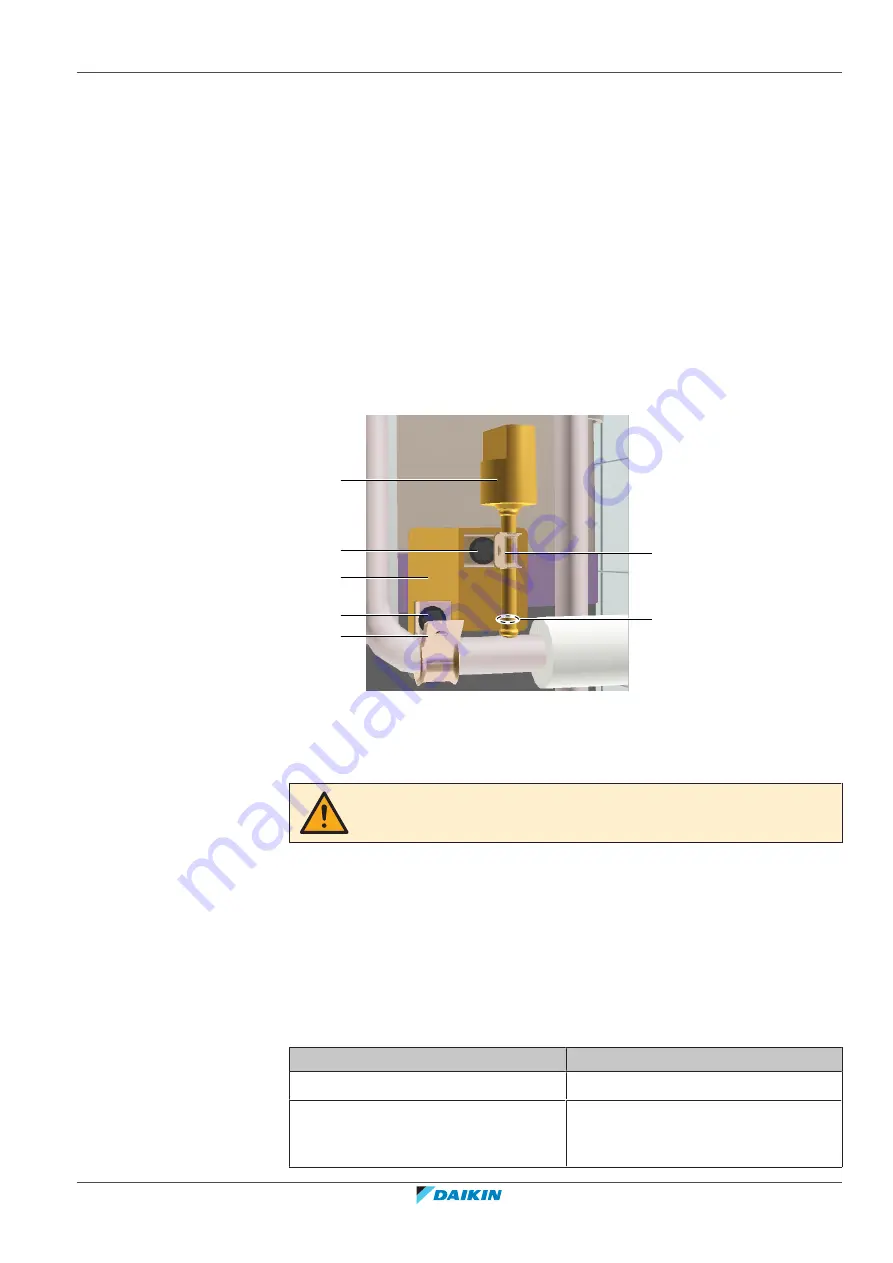
a
b
c
c
d
d
e
a
High pressure switch
b
High pressure switch pipe
c
Screw
d
Clamp
e
Plate
CAUTION
Overheating the pressure switch will damage or destroy it.
4
After soldering is done, stop the nitrogen supply after the component has
cooled‑down.
5
Install the clamps, the screws and the plate.
6
Route the high pressure switch harness towards the appropriate PCB.
7
Connect the high pressure switch connector to the PCB.
8
Install new tie straps to fix the high pressure switch harness.
9
Add
refrigerant
to
the
refrigerant
circuit,
see
368].
Is the problem solved?
Action
Yes
No further actions required.
No
Return to the troubleshooting of the
specific error and continue with the
next procedure.
Summary of Contents for VRV IV+
Page 473: ......
Page 474: ......
Page 475: ......
Page 476: ...ESIE18 15B 2020 05 Copyright 2020 Daikin Verantwortung für Energie und Umwelt ...


