


3
|
Components
Service manual
296
REYQ8~20+REMQ5U7Y1B
VRV IV+ Heat Recovery
ESIE18-15B – 2020.05
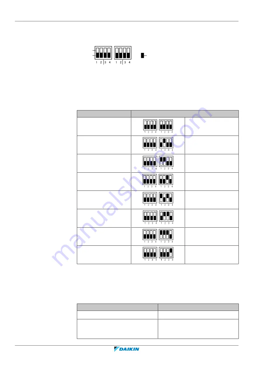
To set the DIP switches of the spare part main PCB
If a spare part main PCB is installed in your unit, the DIP switches need to be set. By
default (factory settings) all switches are in off position.
c
d
e
a
b
a
ON position
b
OFF position
c
DS1
e
DS2
e
Shows the position of a switch
1
Shut the power off.
2
Position the DIP switches for your particular model as shown in the table
below.
Applicable models
Position of DIP switches
REMQ5
All switches are OFF.
REYQ8
DS2-2 is ON.
REYQ10
DS2-1 and DS2-2 are ON.
REYQ12
DS2-3 is ON.
REYQ14
DS2-1 and DS2-3 are ON.
REYQ16
DS2-2 and DS2-3 are ON.
REYQ18
DS2-1 and DS2-2 and
DS2-3 are ON.
REYQ20
DS2-4 is ON.
3
After replacing main PCBA1P , a test run is required. Refer to Installation
Manual for Test Run. If test run is not carried out successfully, U3 Error will be
triggered.
4
If PJ or UA or U7 Errors are triggered after spare part main PCB A1P
replacement, check the position of the switches accordingly. If the error is not
solved then consult the related error code for troubleshooting.
Is the problem solved?
Action
Yes
No further actions required.
No
and continue with the next procedure.
Summary of Contents for VRV IV+
Page 473: ......
Page 474: ......
Page 475: ......
Page 476: ...ESIE18 15B 2020 05 Copyright 2020 Daikin Verantwortung für Energie und Umwelt ...


