


3
|
Components
Service manual
335
REYQ8~20+REMQ5U7Y1B
VRV IV+ Heat Recovery
ESIE18-15B – 2020.05
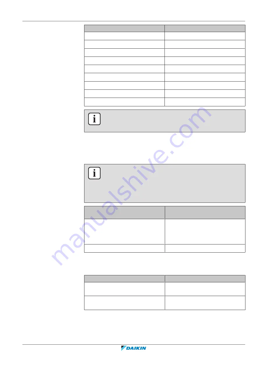
V (DC)
Detected pressure (MPa)
2.8
1.32
2.9
1.37
3.0
1.43
3.1
1.49
3.2
1.54
3.3
1.60
3.4
1.66
3.5
1.72
3.6
1.77
INFORMATION
The refrigerant pressure sensor connector MUST be plugged into the appropriate
PCB.
4
Measure the voltage on X31A: pins 2–3 (= refrigerant pressure output signal)
on the main PCB.
5
Check that the measured voltage is in line with the expected voltage through
the read refrigerant pressure.
INFORMATION
Connect the service monitoring tool to the unit or use field settings mode 1‑43 (see
455]) to monitor the low pressure.
If the measured output voltage value matches the voltage determined through the
measured pressure, but the pressure via the service monitoring tool is NOT correct,
replace the applicable PCB.
The measured voltage is inside the
expected range?
Action
Yes
Refrigerant pressure sensor is OK.
Return to the troubleshooting of the
specific error and continue with the
next procedure.
No
Continue with the next step.
6
Unplug the refrigerant pressure sensor connector X31A and measure the
voltage (power supply) between pins 3–4 on main PCB.
Result:
The measured voltage MUST be +5 V DC.
Is the measured v5 V DC?
Then
Yes
Replace the refrigerant pressure sensor,
see
336].
No
Perform a check of the main PCB, see
290].
Summary of Contents for VRV IV+
Page 473: ......
Page 474: ......
Page 475: ......
Page 476: ...ESIE18 15B 2020 05 Copyright 2020 Daikin Verantwortung für Energie und Umwelt ...


