


3
|
Components
Service manual
338
REYQ8~20+REMQ5U7Y1B
VRV IV+ Heat Recovery
ESIE18-15B – 2020.05
Is the solenoid valve coil firmly fixed
and not visually damaged?
Action
Yes
Perform an electrical check of the
solenoid valve, see
No
Fix or replace the solenoid valve coil,
see
To perform an electrical check of the solenoid valve
Prerequisite:
First perform a mechanical check of the solenoid valve, see
1
Unplug the solenoid valve connector from the appropriate PCB.
2
Measure the resistance of the solenoid valve coil.
Result:
The measured value MUST be 1.34 kΩ ± 5%.
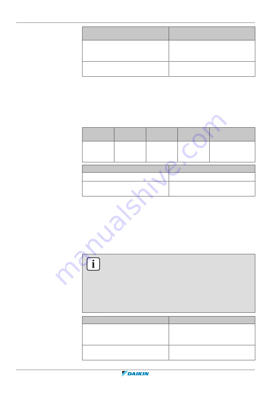
Name
Symbol
Location
(PCB)
Connector
Winding resistance
Liquid pipe
solenoid
valve
Y2S
A1P
X15A
1.34 kΩ
Is the measured value correct?
Action
Yes
Continue with the next step.
No
Replace the solenoid valve coil, see
3
Re‑connect the solenoid valve connector to the appropriate PCB.
4
Turn ON the power using the respective circuit breaker.
5
Turn on the unit using the user interface.
6
Measure the voltage (power supply) on the solenoid valve connection on the
PCB. The measured voltage MUST be:
▪
0 V AC when the solenoid valve is closed
▪
230 V AC when the solenoid valve is triggered open
INFORMATION
Check the solenoid valve status using the service monitoring tool.
On a single unit the solenoid valve is open when the unit is operating.
On a multi combination:
▪
If there is enough liquid compared to the load, the solenoid valve may be
switched OFF in one of the units.
▪
When in high load operation, the solenoid valve will most likely be open on all
units.
Are the measured voltages correct?
Action
Yes
Perform a position check of the
solenoid valve, see
No
Perform a check of the main PCB, see
290].
Summary of Contents for VRV IV+
Page 473: ......
Page 474: ......
Page 475: ......
Page 476: ...ESIE18 15B 2020 05 Copyright 2020 Daikin Verantwortung für Energie und Umwelt ...


