3
|
Components
Service manual
353
REYQ8~20+REMQ5U7Y1B
VRV IV+ Heat Recovery
ESIE18-15B – 2020.05
b
a
b
c
d
e
f
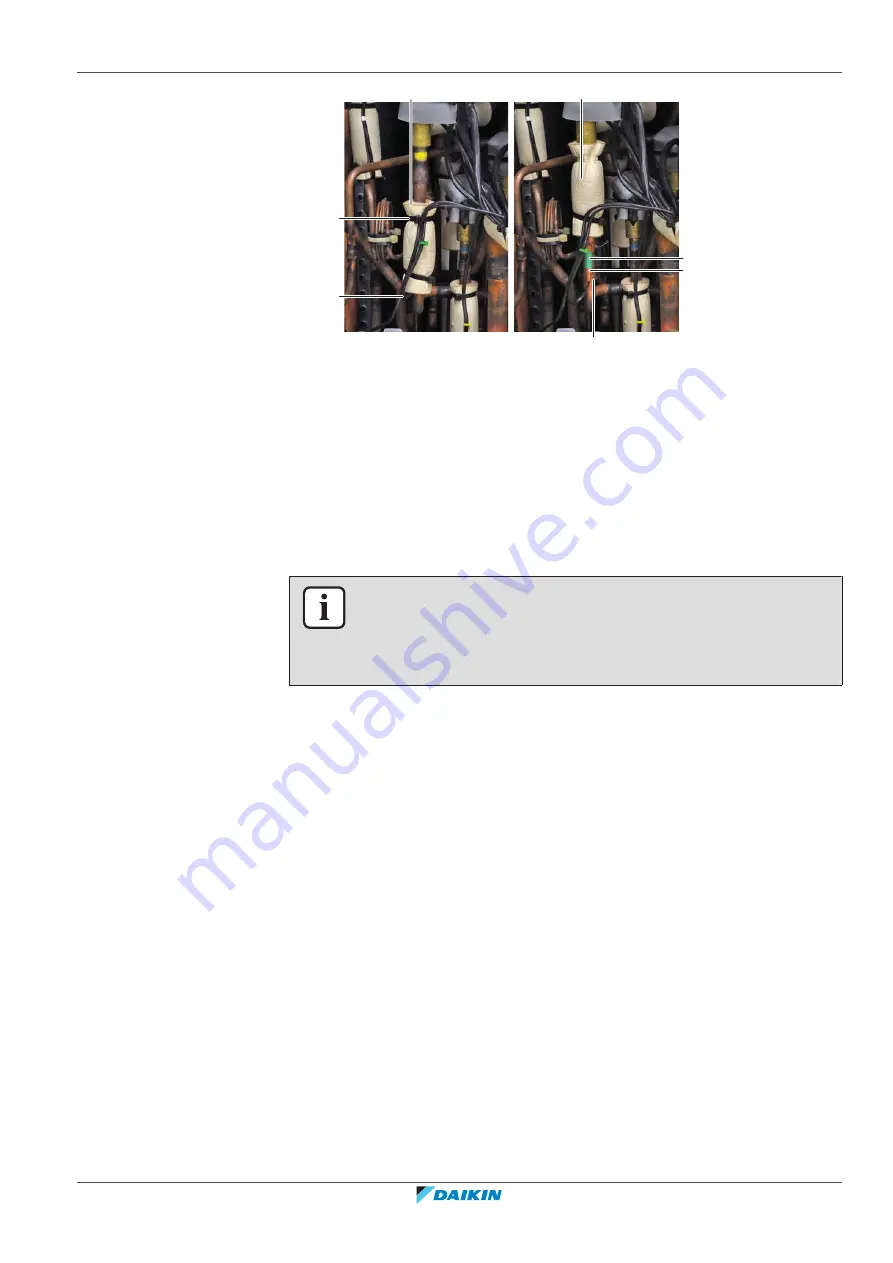
a
Tie strap
b
Insulation
c
Thermistor wire
d
Clip
e
Thermistor holder
f
Thermistor
3
Slide the insulation aside.
4
Pull the clip that fixes the thermistor.
5
Remove the thermistor from the thermistor holder.
6
Cut all tie straps that fix the thermistor harness.
7
Disconnect the thermistor connector from the appropriate PCB.
INFORMATION
Some of the thermistors are wired to the same connector. See connector and pin
information of the thermistors at the start of the electrical check procedure and
385]. ALWAYS replace the complete set of thermistors wired
to the same connector.
8
When removing the complete set of thermistors wired to the same connector:
▪
Remove all other thermistors wired to the connector from their thermistor
holder,
▪
Disconnect the thermistor connector from the appropriate PCB,
▪
Remove the complete set of thermistors.
9
To install the thermistor, see
352].
To install the thermistor
1
Pull the clip and install the thermistor in the specific thermistor holder. Make
sure the clip is in the correct position (blocking the thermistor).
Summary of Contents for VRV IV+
Page 473: ......
Page 474: ......
Page 475: ......
Page 476: ...ESIE18 15B 2020 05 Copyright 2020 Daikin Verantwortung für Energie und Umwelt ...