


6
|
Technical data
Service manual
393
REYQ8~20+REMQ5U7Y1B
VRV IV+ Heat Recovery
ESIE18-15B – 2020.05
6.2.2 Wiring diagram: Branch selector box
Branch selector box BS1Q-A
Notes
1
This wiring diagram applies to the BS unit only.
2
Symbols (see below).
3
When using the cool /heat selector (optional accessory), connect it to
terminals A, B and C on X2M.
4
As for wiring to the indoor unit (F1) (F2) and outdoor unit (F1) (F2).
5
Symbols show as follows: (BLU: Blue, RED: Red).
6
Use copper conductors only.
7
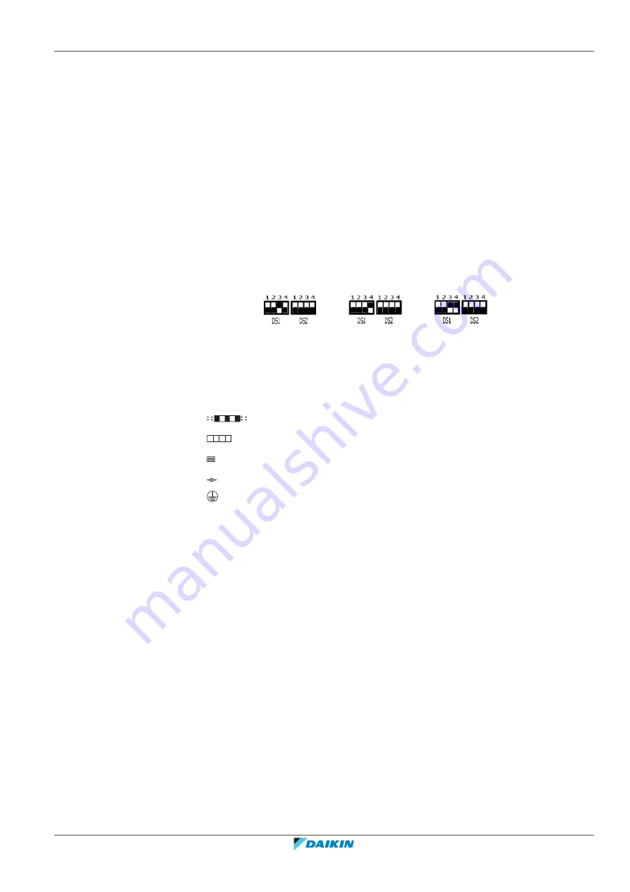
DIP switch (DS1, DS2) initial settings are as follows:
On
Off
On
Off
On
Off
For using DIP switch (DS1, DS2), refer to installation manual or “service
precaution” label on EL. Compo box cover.
Symbols:
Field wiring
Terminal block
Connector
Terminal
Protective earth
Legend for wiring diagram: BS1Q-A
A1P
Printed circuit board
DS1
DIP switch
F1U,
Fuse (T 3.15 A / 250 V)
PS
Switching power supply
X1M
Terminal strip
X1M (A1P)
Terminal strip (control)
X2M
Terminal strip (C/H selector)
Y1E
Electric expansion valve (subcool)
Y2E
Electric expansion valve (main discharge)
Y3E
Electric expansion valve (main suction)
Z1C
Noise filter (ferrite core)
Connector for optional parts
X2A
Connector (wiring external control adapter for outdoor unit)
X38A
Connector (adapter for multi tenant)
Summary of Contents for VRV IV+
Page 473: ......
Page 474: ......
Page 475: ......
Page 476: ...ESIE18 15B 2020 05 Copyright 2020 Daikin Verantwortung für Energie und Umwelt ...


