6
|
Technical data
Service manual
433
REYQ8~20+REMQ5U7Y1B
VRV IV+ Heat Recovery
ESIE18-15B – 2020.05
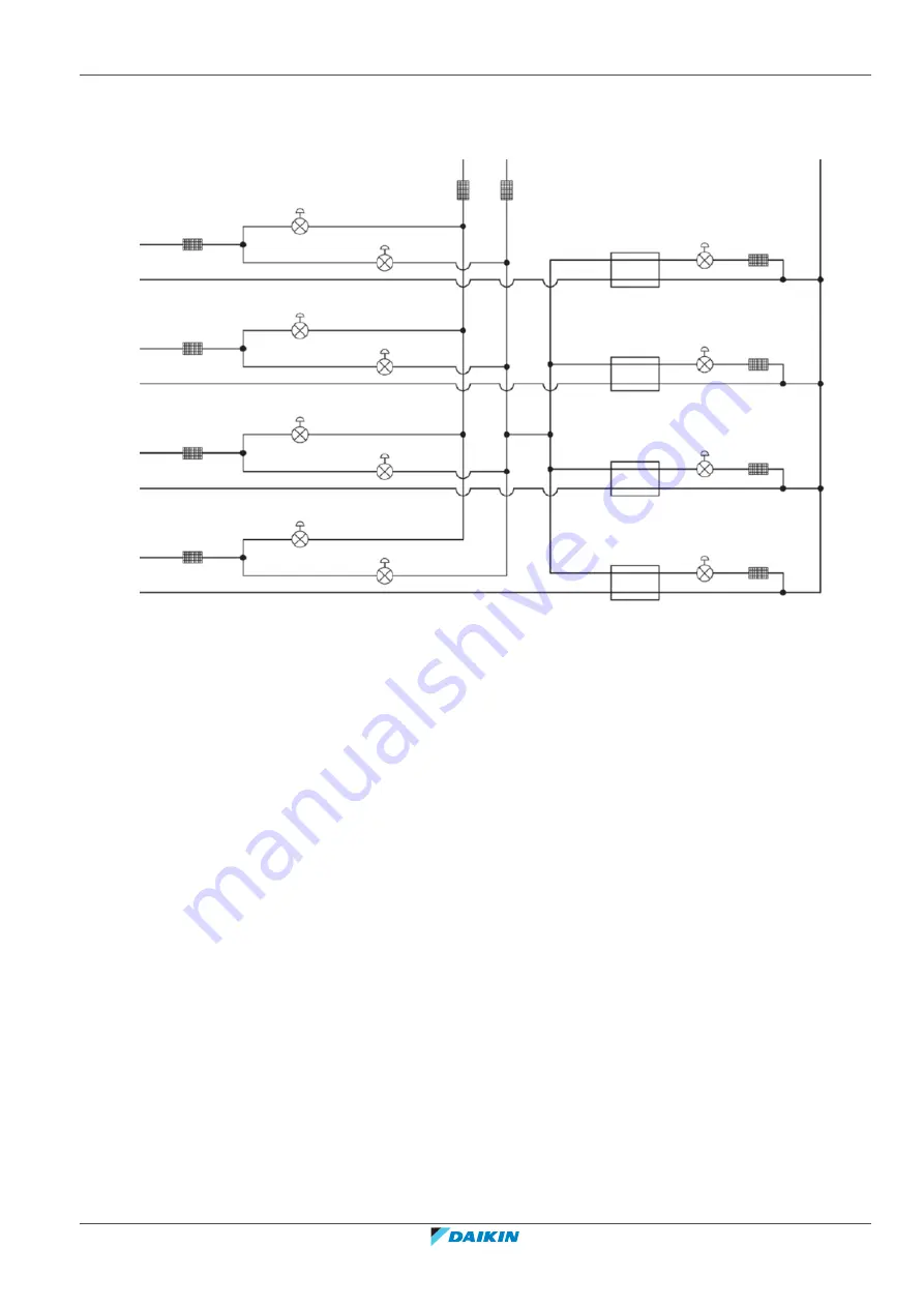
BS4Q-A Branch selector box Piping diagram
a
b
e
f
d
e
f
d
e
f
d
e
f
d
c
d
h
g
d
h
g
d
i1
j1
i2
j2
i3
j3
i4
j4
h
g
a
Liquid pipe (outdoor unit side pipe connections)
b
Suction gas pipe (outdoor unit side pipe connections)
c
High pressure/low pressure gas pipe (outdoor unit side pipe connections)
d
Filter
e
Subcool heat exchanger (double-tube)
f
Subcool electronic expansion valve
g
Suction pipe electronic expansion valve
h
High pressure/low pressure electronic expansion valve
i1, j1
Indoor unit A
*
i2, j2
Indoor unit B
*
i3, j3
Indoor unit C
*
j4, j4
Indoor unit D
*
*
i = gas pipe, j = liquid pipe
Summary of Contents for VRV IV+
Page 473: ......
Page 474: ......
Page 475: ......
Page 476: ...ESIE18 15B 2020 05 Copyright 2020 Daikin Verantwortung für Energie und Umwelt ...


