3
|
Components
Service manual
270
REYQ8~20+REMQ5U7Y1B
VRV IV+ Heat Recovery
ESIE18-15B – 2020.05
2
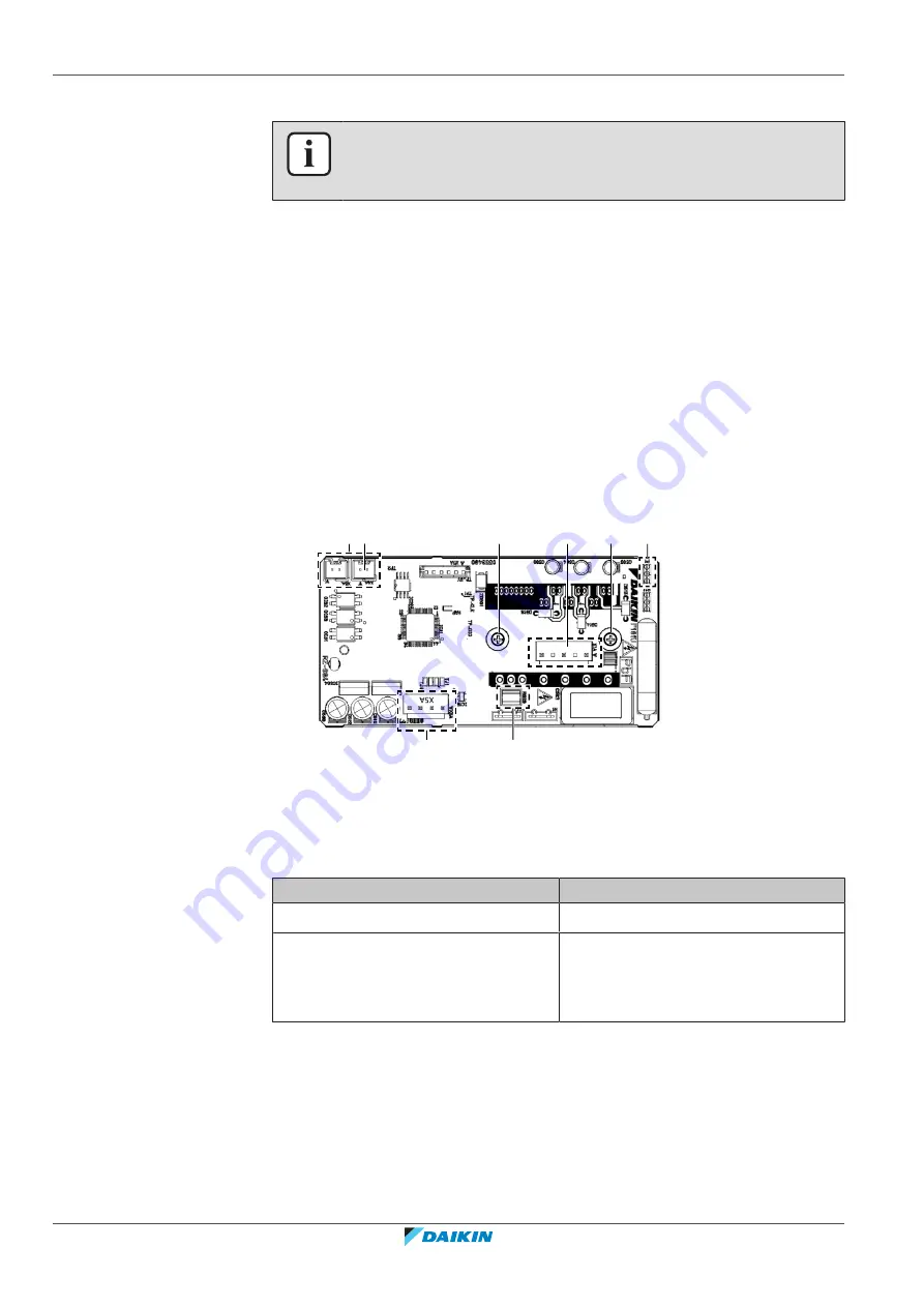
Disconnect all other connectors from the fan inverter PCB.
INFORMATION
Bridge connector X4A is not supplied with the spare part PCB. Transfer the bridge
connector X4A
3
Loosen and remove the 2 screws that fix the fan inverter PCB to the heat sink
plate.
4
Carefully pull the PCB at the side and unlatch the PCB supports one by one
using a small pair of pliers.
5
To install the new fan inverter PCB, see
To install the fan inverter PCB
1
Clean the heat sink surface and apply a thin layer of heat sink compound to
the heat sink surface.
2
Install the fan inverter PCB on its correct location.
3
Latch the PCB supports using a small pair of pliers to fix the PCB.
4
Install and tighten the 2 screws to fix the fan inverter PCB to the heat sink
plate.
a
b
b
a
d
c
a
a
a
Connector
b
Screw
c
Connector X1A
d
Connector X4A
5
Connect all connectors to the fan inverter PCB.
6
Reinstall connector X4A which you recuperated from the removed PCB.
Is the problem solved?
Action
Yes
No further actions required.
No
PCB and continue with the next
procedure.
3.9 High pressure switch
3.9.1 Checking procedures
To perform an electrical check of the high pressure switch
Prerequisite:
Stop the unit operation via the central controller.
Summary of Contents for VRV IV+
Page 473: ......
Page 474: ......
Page 475: ......
Page 476: ...ESIE18 15B 2020 05 Copyright 2020 Daikin Verantwortung für Energie und Umwelt ...


