Si-95
Failure Diagnosis for Inverter System
Troubleshooting Inverter K Series
113
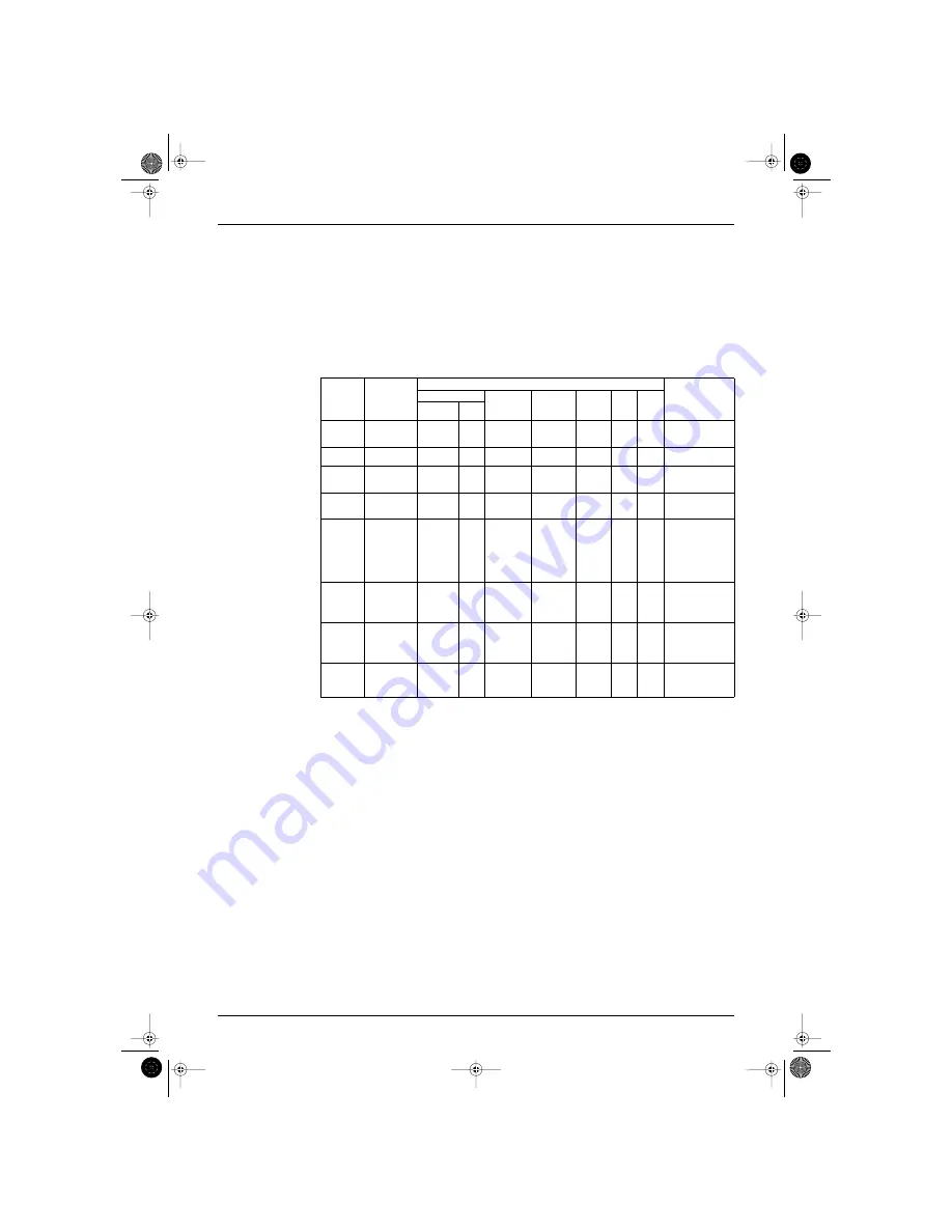
3. Failure Diagnosis for Inverter System
3.1
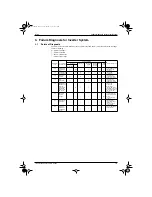
Points of Diagnosis
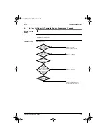
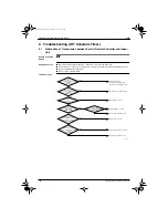
The main causes for each malfunction code are given in the table below. (For details refer to the next page
and those following.)
: Failure is probable
8
: Failure is possible
: Failure is improbable
— : Failure is impossible
Malfunction
code
Contents of
malfunction
Location of failure
Point of diagnosis
Inverter
Compressor
Refrigerant
system
Outdoor
unit PC
board
Other
Field
cause
PC board
power unit
Other
L4
Radiator fin
temperature
rise
—
—
—
—
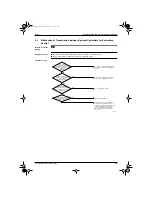
Is the intake port of
the radiator fin
clogged?
L5
Instantaneous
over-current
8
—
—
—
—
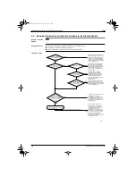
Inspect the
compressor.
L8
Electronic
thermal
—
8
—
—
—
Inspection the
compressor and
refrigerant system.
L9
Stall
prevention
—
8
—
—
—
Inspection the
compressor and
refrigerant system.
LC
Malfunction of
transmission
between
inverter PC
board and
outdoor unit
PC board
8
—
—
—
—
Inspect the
connection
between the
inverter PC board
and outdoor unit PC
board. Next, inspect
the inverter PC
board.
U2
Abnormal
current/
voltage
8
8
—
—
—
•
Inspect the fuse
on the inverter PC
board.
•
Check the DC
voltage.
P1
Over-ripple
protection
8
8
—
—
—
—
8
•
Open phase
•
Current/voltage
imbalance
•
Defect of main
circuit wiring
P4
Defect of
radiator fin
temperature
sensor
8
—
—
—
—
—
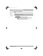
Inspect the radiator
fin thermistor.
SI-95.BOOK Page 113 Friday, March 31, 2000 10:59 AM

