background image

Si-95

Test Operation

Test Operation Inverter K Series

47

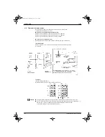
1.3.2

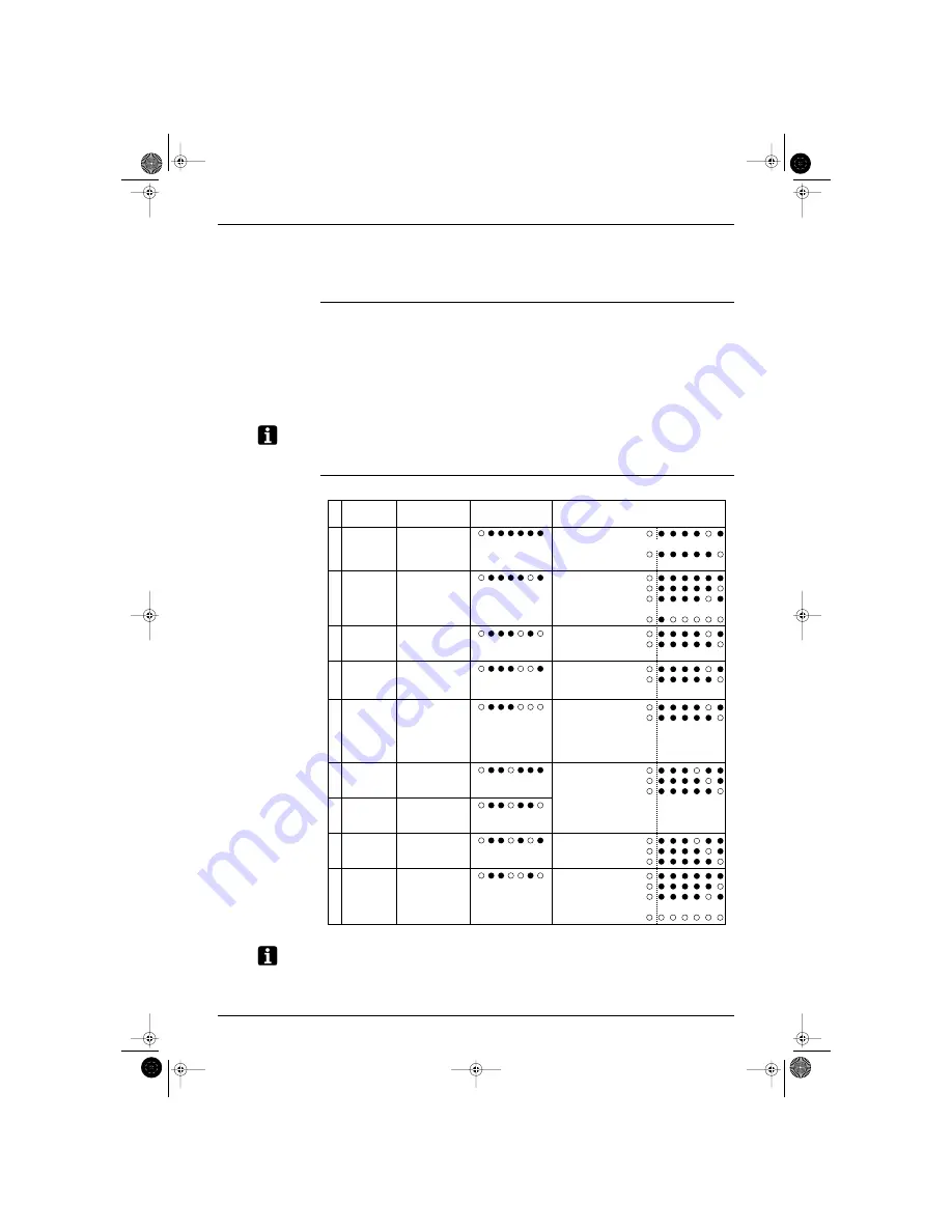
Setting Mode 2

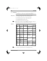
To enter setting mode 2 from setting mode 1 (normal), you must push and hold the MODE button (BS1) for 

5 seconds. (Setting mode 2 cannot be entered while still making settings in setting mode 1.)

Setting procedure

1. Push the SET button and match with the setting item (LED display). (All 9 settings)

2. Push the RETURN button (BS3) and the present settings flicker (LED display). 

3. Push the SET button (BS2) and match with each setting (LED flicker display).

4. Push the RETURN button (BS3) and enter the settings.

5. Push the RETURN button (BS3) and return to the initial status. 

Note:

If you become unsure of how to proceed, push the MODE button (BS1) and return to setting mode 1.

The initial status of setting mode 2 is the status of setting item No. 1 in mode 2. 

Setting items

Note:

∗ 

1 : Simultaneous cooling / heating operation is not possible by Emergency operation.

1

2

3

4

5

6

7

8

9

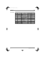
Setting item

EMG

 1

Low noise / 
demand 
address

Forced fan 
switch

Indoor unit 
forced 
operation

Frequency 
fix

Te setting

Tc setting

Defrost 
setting

Not used

Description

Emergency 
operation when 
malfunction 
occurs 

Address for low 
noise / demand 
group operation

Fan of stopped 
indoor unit turns

Allows operation 
of indoor unit 
from outdoor unit

Fixes the 
frequency of the 
inverter 
compressor

5HP···68Hz
8.10HP··86Hz+ON

Low pressure 
setting for 
cooling

High pressure 
setting for 
heating

Temperature 
setting for 
defrost

Airnet address

LED display

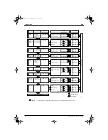
H1P H2P H3P H4P H5P H6P H7P

LED display

H1P H2P H3P H4P H5P H6P H7P

Emergency operation
(Runs only by standard compressor)
Normal operation

Address
Binary number
(6 digits)

Forced fan operation 
(H tap)
Normal operation

Indoor unit forced 
operation
Normal operation

Frequency fix
Normal operation

High
Normal (factory set)
Low

Quick defrost
Normal (factory set)
Slow defrost

Address
Binary number
(6 digits)

0
1
2


63

0
1
2


31

~

~

(VF084)

SI-95.BOOK  Page 47  Friday, March 31, 2000  10:59 AM

Summary of Contents for VRV K

Page 1: ...9 Pressure Equalization Control 23 1 10 Frequency Limit Control by Pressure Equalization 24 1 11 BS Changeover Control 25 1 12 Pump Down Residual Operation 26 1 13 Step Down Safety Control Standby Fo...

Page 2: ...R3T for Gas Pipes 86 2 11 Indoor Unit Malfunction of Thermistor R1T for Air Inlet 87 2 12 Indoor Unit Malfunction of Thermostat Sensor in Remote Controller 88 2 13 Outdoor Unit Actuation of Safety Dev...

Page 3: ...taneous Failure 120 4 7 Outdoor Unit Malfunction of Inverter Radiating Fin Temperature Rise Sensor 121 4 8 Outdoor Unit Inverter Over Ripple Protection 122 5 Troubleshooting OP Central Remote Controll...

Page 4: ...de Modules 141 2 1 Method of Replacing The Inverter s Power Transistors and Diode Modules 141 3 Precaution 142 3 1 PC Boards and Remote Controller s Mode No 142 4 Typical Wiring Mistakes 143 4 1 Typic...

Page 5: ...bling the equipment for a repair Working on the equipment that is connected to a power supply can cause an electrical shook If it is necessary to supply power to the equipment to conduct the repair or...

Page 6: ...shock excessive heat generation or fire When relocating the equipment make sure that the new installation site has sufficient strength to withstand the weight of the equipment If the installation site...

Page 7: ...old battery to prevent children from swallowing it If a child swallows the coin battery see a doctor immediately Warning Caution Installation of a leakage breaker is necessary in some cases depending...

Page 8: ...ectrical shock Be sure to check the drainage of the indoor unit after the repair Faulty drainage can cause the water to enter the room and wet the furniture and floor Caution Icon Type of Information...

Page 9: ...and so you can provide fast and reliable after sales service Although the contents of the manual may be insufficient in some areas we hope that you will use it to the best of your ability The service...

Page 10: ...Introduction Si 95 x SI 95 BOOK Page x Friday March 31 2000 10 59 AM...

Page 11: ...Information Inverter K Series 1 Part1 General Information Inverter K Series 1 Outline 2 1 1 System Outline 2 1 2 Allowed Range of Indoor Unit and BS Unit Connection 3 SI 95 BOOK Page 1 Friday March 31...

Page 12: ...indoor units Outside temperature of 35 C for operation mode A 0 C for operation mode D and typical seasonal outside temperatures for others No 1 No 2 No 3 No 4 BS unit Outdoor unit RSEYP10K 10HP Indo...

Page 13: ...table indoor units Max number of connectable indoor units Range A Total indoor unit capacity RSEY8KLY1 11 2 to 29 1kW 13 units RSEY10KLY1 14 to 36 4kW 16 units Range B Total indoor unit capacity allow...

Page 14: ...Outline Si 95 4 General Information Inverter K Series SI 95 BOOK Page 4 Friday March 31 2000 10 59 AM...

Page 15: ...0 1 8 Defrost 21 1 9 Pressure Equalization Control 23 1 10 Frequency Limit Control by Pressure Equalization 24 1 11 BS Changeover Control 25 1 12 Pump Down Residual Operation 26 1 13 Step Down Safety...

Page 16: ...Functions Si 95 6 Functions Inverter K Series 1 Functions 1 1 Outdoor Unit Refrigerant Diagrams RSEY8K 10KLY1 SI 95 BOOK Page 6 Friday March 31 2000 10 59 AM...

Page 17: ...change H Solenoid valve for liquid pressure Y6S This valve opens a bypass to send hot gas to the receiver and controls the liquid pressure I Pressure sensor high pressure red SENPH This semiconductor...

Page 18: ...valve discharge side Y3S Turn ON this valve to operate of discharge oil return when indoor unit is set for heating Connect indoor unit gas pipe and outdoor unit discharge pipe C Solenoid valve Drift p...

Page 19: ...0 0 1 0 1 0kg cm2 Fusible plug FPG 3D 70 75 C Sensor SENPH Pressure sensor PS8030A 0 30kg cm2 0 2 94MPa SENPL Pressure sensor PS8030A 0 10kg cm2 0 0 98MPa R1T Thermistor for outdoor air 3 5 360K R2 1T...

Page 20: ...Functions Si 95 10 Functions Inverter K Series 1 3 Flow of Refrigerant in Each Operation Mode 1 3 1 Cooling High pressure Low pressure SI 95 BOOK Page 10 Friday March 31 2000 10 59 AM...

Page 21: ...Si 95 Functions Functions Inverter K Series 11 1 3 2 Heating High pressure Low pressure SI 95 BOOK Page 11 Friday March 31 2000 10 59 AM...

Page 22: ...Functions Si 95 12 Functions Inverter K Series 1 3 3 Simultaneous Cooling and Heating High pressure Low pressure SI 95 BOOK Page 12 Friday March 31 2000 10 59 AM...

Page 23: ...Si 95 Functions Functions Inverter K Series 13 1 3 4 Discharge Oil Return Defrost High pressure Low pressure SI 95 BOOK Page 13 Friday March 31 2000 10 59 AM...

Page 24: ...Functions Si 95 14 Functions Inverter K Series 1 3 5 Suction Oil Defrost High pressure Low pressure SI 95 BOOK Page 14 Friday March 31 2000 10 59 AM...

Page 25: ...constant superheat SH level at the outlet of the outdoor heat exchanger evaporator SHs Ts Te SHs 5 C Ts1 Suction pipe temperature R4 1T Ts2 Suction pipe temperature R4 2T 3 Heat exchanger PI control P...

Page 26: ...peration Heat operation COND COND H ON 1 COND COND L ON 1 COND COND H OFF 1 COND COND L OFF 1 COND EVAP H ON 2 COND EVAP L ON 2 COND EVAP H OFF 2 COND EVAP L OFF 2 COND EVAP L OFF 3 COND EVAP L OFF 4...

Page 27: ...pressure after the compressor stops fully close the indoor unit s electronic expansion valve for 10 minutes 1 5 2 Soft Start The following control is carried out to protect the compressor and inverter...

Page 28: ...Lay Up Start If the compressor hasn t run for a long time and the refrigerant isn t circulated foaming could cause a lack of oil when the compressor is started at the next time It should therefore pe...

Page 29: ...then reverts to normal operation If oil pressure equalization is not achieved during 5 minutes by stopping or step down control oil pressure equalization is carried out when the standard compressor s...

Page 30: ...F EEV 2000pls Outdoor Unit Fan H ON Outdoor Unit Heat Exchanger Condenser 4 Way Valve OFF Injection 1 Td Protection Control Injection 2 Td Protection Control Hot Gas ON at Lp 0 3k 4 Minutes Elapsed Td...

Page 31: ...on M Tcoil R2 1T R2 2T 10 C 3 If position H Tcoil R2 1T R2 2T 8 C Because defrost operation is carried out set to the H position if frost builds up easily and set to L if not Factory set is position M...

Page 32: ...12 5 C Pc 20 5k 10 Minutes Elapsed Since Defrost Operation Start Step 3 BS solenoid valve changeover Compressor 38Hz OFF EEV 2000pls Outdoor Unit Fan OFF OFF Outdoor Unit Heat Exchanger Condenser 4 W...

Page 33: ...ressure equalization solenoid valve Y1S is ON at following conditions Operating condition of indoor unit with thermostat ON is different from the condition of BS unit s solenoid valve see page 25 Not...

Page 34: ...ty is limited to prevent abnormal noise caused by the equalizing operation Operating conditions During the first 30 seconds the following operations are conducted Equalizing operation demand issued No...

Page 35: ...ion 4 Oil return defrost Oil return defrost complete Discharge defrost Discharge oil return Suction defrost Suction oil return VF006 Condition Indoor unit operating condition Y3S Y2S Y1S ON Open OFF C...

Page 36: ...al operation Secondary side heat exchanger 4 way valve Y2R is ON Discharge pipe thermistor R3 1T on inverter side 95 C or lower OR Outside air temperature thermistor R1T 0 C When compressor continuous...

Page 37: ...operation Hot gas bypass valve ON 106Hz OFF or 60Hz ON Injection valve ON Lp 1 7kg cm 0 167MPa Forced thermostat OFF Up to 2 times in 30 minutes E4 stop due to malfunction Hot gas bypass valve ON VF0...

Page 38: ...OFF and discharge super heating DSH continues for 10 minutes at temperature difference of less than 10 C the inverter standard compressor are controlled at 76 Hz or less OFF for 3 minutes Control Acco...

Page 39: ...MPa Step2 1 high pressure 19 kg cm2 1 86 MPa Low noise control reduces capacity by limiting the fan speed and compressor frequency The load when heating is particularly large at night when the outdoor...

Page 40: ...to approx 70 Demand 2 Holds electric power consumption down to approx 40 Demand 3 Forced thermostat OFF An optional external control adaptor of outdoor units is required for demand control For method...

Page 41: ...in 20 stages by microcomputer Commercial power supply compressor off Frequency 30Hz OFF 34Hz OFF 38Hz OFF 42Hz OFF 48Hz OFF 54Hz OFF 60Hz OFF 68Hz OFF 76Hz OFF 86Hz OFF 96Hz OFF 106Hz OFF Commercial...

Page 42: ...ength of piping and indoor load The range is 10 C target Te 5 5 C Piping length is determined automatically during oil return operation Target Tc becomes 3 C higher when indoor load is large Target Tc...

Page 43: ...left continue for 30 min VF008 While compressor is running and 4 way valve ON heating cycle and Evaporator outlet superheat temperature 20 C difference and Outdoor unit electronic expansion valve 200...

Page 44: ...g Thermostat is ON 1 The objective of residual operation is to completely drain any moisture adhering to the fin of the indoor unit heat exchanger when the thermostat goes off during cooling operation...

Page 45: ...s operation 5 seconds stop 5 minutes operation cycle ends operation continues until the switch is reset 1 19 4 When the Float Switch is Tripped and AF is Displayed on the Remote Controller Note If the...

Page 46: ...d corner types P0 P1 P2 P4 P3 P0 P1 P2 P4 P3 P0 P0 P1 P2 P4 P4 P2 P1 P0 P4 P4 P3 P2 P1 P0 P3 Existing position Draft prevention position Standard Setting position Ceiling soiling prevention position D...

Page 47: ...g Assuming the preset temperature in the figure above is 24 C and the suction temperature has changed from 18 C to 30 C A F This example also assumes there are several other air conditioners the VRV s...

Page 48: ...mperature is higher than the preset temperature Ex When heating Assuming the preset temperature in the figure above is 24 C and the suction temperature has changed from 18 C to 28 C A F This example a...

Page 49: ...tion operation in accordance with the following conditions and is also set in accordance with the conditions given below Conditions for starting freeze prevention Temperature is 1 C or less for total...

Page 50: ...Functions Si 95 40 Functions Inverter K Series SI 95 BOOK Page 40 Friday March 31 2000 10 59 AM...

Page 51: ...04A61 TA104A62 52 1 6 Cool Heat Mode Switching 56 1 7 Low Noise Operation 58 1 8 Demand Control 59 1 9 Wiring Check Operation 60 1 10 Indoor Field Setting 61 1 11 Centralized Control Group No Setting...

Page 52: ...or master power supply to be set automatically Outdoor unit LED HWL H2P On Test lamp H2P Flicker Can be set while in operation Indoor unit If the ON OFF button is pushed during the aforementioned oper...

Page 53: ...Si 95 Test Operation Test Operation Inverter K Series 43 1 2 Outdoor Unit PC Board Ass y RSEY8K 10K SI 95 BOOK Page 43 Friday March 31 2000 10 59 AM...

Page 54: ...hold for 5 sec to start wiring check Reset button Push and hold for 5 sec if the indoor unit s PC board has been replaced or there has been a change in the combination of indoor and outdoor units such...

Page 55: ...f how to proceed push the MODE button and return to setting mode 1 You don t have to perform power supply reset after changing settings in setting mode 1 including SS1 cool heat selection switch on th...

Page 56: ...sequential start to OFF Setting complete GROUP MASTER cool heat selection ON low noise OFF sequential start MODE TEST L N O P SEQ HWL START H1P H2P H3P H4P H5P H6P H7P SET MODE TEST L N O P SEQ HWL ST...

Page 57: ...operation is not possible by Emergency operation 1 2 3 4 5 6 7 8 9 Setting item EMG 1 Low noise demand address Forced fan switch Indoor unit forced operation Frequency fix Te setting Tc setting Defros...

Page 58: ...an switch 3 S Forced fan operation H tap Normal operation Allows operation of indoor unit from outdoor unit Indoor unit forced operation 4 S Frequency fix Normal operation Fixes the frequency of the i...

Page 59: ...set Low Defrost temperature setting for defrost Quick defrost Normal factory set Slow defrost EMG emergency operation when malfunction occurs ON OF Push the SET button and match with the LEDs No 1 15...

Page 60: ...one units excluding outdoor and BS units 0 63 units Lower 6 digits No 7 8778777 Number of outdoor units 0 63 units Lower 6 digits No 8 8778778 Number of BS units 0 128 units Lower 4 digits upper No 9...

Page 61: ...oor unit of small capacity as the third unit in the sequence Method of Sequential Start 1 Power supply wiring Must be wired as a group to the power supply 2 Wiring Connect transmission wiring to termi...

Page 62: ...its connected in a DIII NET you can simultaneously select cool heat mode for several outdoor units in the system and it enables demand control and low noise control Part names and functions Note 1 SS2...

Page 63: ...Switch settings on adaptor printed circuit board SS1 BOTH is selected when demand control is carried out at the same time SS2 DS1 2 BOTH C H DE C H SL302 OFF ON OFF SL303 SS1 When demand control is us...

Page 64: ...nning noise can be reduced by 2 3dB by controlling capacity of outdoor unit System general When each system is set to the same address the same demand control operation is conducted Common Address set...

Page 65: ...Max 150 m Run separate from power line in order to prevent malfunction Installation positions Model series Installation box plate Installation position Outdoor unit Function unit EXIII Not necessary...

Page 66: ...oller 2 Set cool heat individually for all BS unit systems using the cool heat select remote controller 3 Set cool heat individually for all BS unit systems using the cool heat central remote controll...

Page 67: ...nverter K Series 57 1 6 3 Set cool heat individually for all BS unit systems using the cool heat central remote controller Install the External control adaptor for outdoor unit in BS unit SI 95 BOOK P...

Page 68: ...et low noise operation to ON Setting mode 2 Match low noise operation and demand control address with address of outdoor unit external control adaptor 2 Outdoor unit external control adaptor setting F...

Page 69: ...t field setting 2 Outdoor unit external control adaptor setting Function switch SS1 Set to BOTH or DE Address setting switches DS1 DS2 Match with outdoor unit low noise operation and demand control ad...

Page 70: ...running TEST H2P lights and goes off when finished If TEST H2P flickers wiring check operation failure push and hold the RESET button BS5 for 5 seconds and then repeat the procedure from the beginnin...

Page 71: ...has been selected push the time mode button and select the indoor unit No to be set Note This operation is not required when setting as a group 4 Push the button and select the first code No 5 Push th...

Page 72: ...Use No use 3 Display time to clean air filter calculation Set when filter sign is not to be displayed Display No display 12 22 0 Optional accessories output selection field selection of output for ad...

Page 73: ...No display 4 Set the group No for each group with the button The group No increases in the manner of 1 00 1 01 1 15 2 00 4 15 However the unified ON OFF controller displays only the group No within th...

Page 74: ...eration then enters the field set mode 2 Set mode No 00 with button 3 Set the group No for each group with button advance backward 4 Enter the selected group numbers by pushing button 5 Push button an...

Page 75: ...n 1 Continue pushing OPERATION MODE SELECTOR bottun on remote controller which is not displaying changeover under control for about 4 seconds The display of CHANGEOVER UNDER CONTROL on all remote cont...

Page 76: ...VER UNDER CONTROL 1 Set to Cool Heat Auto switch to the operation mode set by the master remote controller However they can switch to FAN operation and from COOL to DRY If you set a Master remote cont...

Page 77: ...ng Blinking Blinking C5 Indoor unit Malfunction of thermistor R3T for gas pipes loose connection disconnection short circuit failure Blinking Blinking Blinking C9 Indoor unit Malfunction of thermistor...

Page 78: ...to failure of electronic expansion valve Blinking Blinking Blinking U1 Negative phase open phase Blinking Blinking Blinking U2 Power supply insufficient or instantaneous failure Blinking Blinking Blin...

Page 79: ...eption beeps twice and then locate the upper code 5 Push the operation mode selector button and the lower digit of the malfunction code blinks 6 Push the time mode button until signal reception beeps...

Page 80: ...de Model FXYA FXYC FXYK FXYF FXYH FXYS FXYL FXYM Type VRV System Inverter K Series Other models VRV System Display A A 1 Outdoor model code Model RSXY Unit Malfunction code Inspection Normal display N...

Page 81: ...unit No to be set with the time mode Selected the unit No with button for wireless remote controller 3 Make the settings required for each mode Modes 41 44 45 Before setting press button and make con...

Page 82: ...electing the unit No with the button you can turn the fan of each indoor unit on forced ON individually 4 4 4 44 4 4 4 Individual setting Set the fan speed and air flow direction by each unit Select t...

Page 83: ...91 2 16 Outdoor Unit Actuation of Low Pressure Sensor 92 2 17 Outdoor Unit Malfunction of Moving Part of Electronic Expansion Valve Y1E 93 2 18 Outdoor Unit Abnormal Discharge Pipe Temperature 94 2 1...

Page 84: ...r 121 4 8 Outdoor Unit Inverter Over Ripple Protection 122 5 Troubleshooting OP Central Remote Controller 123 5 1 Malfunction of Transmission between Central Remote Controller and Indoor Unit 123 5 2...

Page 85: ...rge pipe thermistor R3T 8 96 J5 Outdoor unit Malfunction of thermistor R4T for suction pipe 8 97 J6 Outdoor unit Malfunction of thermistor R2T for heat exchanger 8 98 JA Outdoor unit Malfunction of di...

Page 86: ...fin temperature rise sensor 8 122 Malfunction code Optional controllers for centralized control Malfunction contents Page UE Central remote controller Schedule timer Malfunction of transmission betwe...

Page 87: ...indoor unit PC board Troubleshooting VF029 Indoor unit PC board replacement Actuation of external protection device Change the second code No to 01 or 02 External protection device is connected to ter...

Page 88: ...ng Inverter K Series 2 2 Indoor Unit PC Board Defect Remote Controller Display A A A A1 1 1 1 Supposed Causes Defect of indoor unit PC board Troubleshooting Replace the indoor unit PC board SI 95 BOOK...

Page 89: ...t circuit connector or float switch and turn on again YES YES YES YES Defect of indoor unit PC board Loose connection of connector NO NO NO YES YES NO NO YES NO YES NO NO The float switch is connected...

Page 90: ...or and PC board Troubleshooting Connect the wiring and turn on again Fix the wiring and turn on again YES NO NO NO YES NO Replace the indoor unit PC board Replace the fan motor Is the wiring from the...

Page 91: ...Replace indoor unit PC board NO NO YES NO YES NO YES YES NO Indoor unit is a model equipped with a swing flap function The swing motor works when the power supply is turned off and then back on When t...

Page 92: ...y VF033 After connecting turn the power supply off and then back on Replace the moving part of the electronic expansion valve YES YES NO NO Replace the connecting cable If you turn the power supply of...

Page 93: ...sory leaking Defect of drain pipe upward slope etc Defect of indoor unit PC board Troubleshooting Defect of indoor unit PC board Modify the drain piping YES YES Check if the humidifier unit is leaking...

Page 94: ...city setting adaptor Defect of indoor unit PC board Troubleshooting VF035 Install a capacity setting adaptor Replace the indoor unit PC board NO NO YES YES Replace the indoor unit PC board The indoor...

Page 95: ...or liquid pipe Defect of indoor unit PC board Troubleshooting VF036 Replace the indoor unit PC board Connect the thermistor and turn on again NO NO Replace the thermistor R2T YES YES Connector is conn...

Page 96: ...r R3T for gas pipe Defect of indoor unit PC board Troubleshooting VF037 Replace the indoor unit PC board Connect the thermistor and turn on again NO NO Replace the thermistor R3T YES YES Connector is...

Page 97: ...R1T for air inlet Defect of indoor unit PC board Troubleshooting Replace the indoor unit PC board Connect the thermistor and turn on again NO NO Replace the thermistor R1T YES YES Connector is connec...

Page 98: ...ontroller Remote Controller Display C C C CJ J J J Supposed Causes Defect of remote controller thermistor Defect of remote controller PC board Troubleshooting VF039 The remote controller thermistor or...

Page 99: ...fect of fan motor Defect of capacitor etc VF040 Connector or terminal is connected to X8A X9A of the outdoor unit PC board A1P and X1S X2S Contacts F2C X1S X2S are open Connect the connector or termin...

Page 100: ...nverter K Series 2 14 Outdoor Unit PC Board Defect Remote Controller Display E E E E1 1 1 1 Supposed Causes Defect of outdoor unit PC board A1P Troubleshooting Replace outdoor unit PC board A1P SI 95...

Page 101: ...h pressure switch HPS The outdoor unit PC board s connector is disconnected Is the outdoor unit heat exchanger dirty Defect of outdoor fan Is the refrigerant over charged Operation is normal when turn...

Page 102: ...g 1 Voltage measurement point 2 Refer to pressure sensor pressure voltage characteristics table on P140 VF042 Low pressure at stop due to malfunction is 0 0 kg cm2 Measure the voltage VL of X21A pin N...

Page 103: ...between the connector pins Normal Continuity Approx 300 8 Continuity Approx 150 No continuity VF043 Electronic expansion valve is connected to X14A X15A of outdoor unit PC board A1P Normal when coil...

Page 104: ...Resistance Temperature Characteristics on P138 VF044 Discharge pipe temperature is 135 C or higher Is there a wrong connection of the injection solenoid valves Y3S and Y4S Is there a wrong connection...

Page 105: ...f outdoor unit PC board A1P Troubleshooting The alarm indicator is displayed when the fan is being used also VF045 Resistance is normal when measured after disconnecting the thermistor R1T from the ou...

Page 106: ...nit PC board A1P Troubleshooting The alarm indicator is displayed when the fan is being used also VF046 Resistance is normal when measured after disconnecting the thermistor R3 1T R3 2T from the indoo...

Page 107: ...t PC board A1P Troubleshooting The alarm indicator is displayed when the fan is being used also VF047 Resistance is normal when measured after disconnecting the thermistor R4 1T R4 2T from the indoor...

Page 108: ...PC board A1P Troubleshooting The alarm indicator is displayed when the fan is being used also VF048 Resistance is normal when measured after disconnecting the thermistor R2 1T R2 2T from the indoor u...

Page 109: ...1 Voltage measurement point 2 Refer to pressure sensor pressure voltage characteristics table on P140 VF049 The relationship between the VH and high pressure is normal see 2 when voltage is measured...

Page 110: ...Voltage measurement point 2 Refer to pressure sensor pressure voltage characteristics table on P140 VF050 The relationship between the VH and low pressure is normal see 2 when voltage is measured betw...

Page 111: ...mistor R5T Defect of outdoor unit PC board A1P Troubleshooting VF051 Is the connector is connected to X13A of the outdoor PC board A1P Resistance is normal when measured with thermistor R5T disconnect...

Page 112: ...d with the suction pipe thermistor R4 1T R4 2T and coil thermistor R2 1T R2 2T disconnected from the outdoor unit PC board Out of gas or refrigerant system is clogged Requires check of refrigerant sys...

Page 113: ...1P Troubleshooting VF053 Operation is normal if one place of power supply line phase is replaced Fix the open phase Requires inspection of field power supply section Negative phase Disposal of the pro...

Page 114: ...seconds Fix the indoor outdoor unit transmission wiring YES NO NO YES Has the indoor or outdoor unit PC board been replaced or has the indoor outdoor or outdoor outdoor unit transmission wiring been...

Page 115: ...nit PC board Set one remote controller to SUB turn the power supply off once and then back on There is possibility of malfunction caused by noise Check the surrounding area and turn on again NO NO Usi...

Page 116: ...NO C H SELECT is set to IND Cool heat selection is unified C H SELECT is set to Unfied MAIN NO Is the indoor outdoor unit transmission wiring normal C H SELECT is set to Unfied SUB YES NO Check and se...

Page 117: ...s Defect of remote controller PC board Troubleshooting VF057 SS1 of both remote controllers is set to SUB Set SS1 to MAIN the power supply off once and then back on Set one remote controller to MAIN t...

Page 118: ...refrigerant system Refer to failure diagnosis for U5 malfunction code Re diagnose by display after passage of 2 minutes or more Refer to failure disgnosis for UA malfuntion code NO NO Refer to failure...

Page 119: ...l of outdoor unit RSEY 8K Max 13 units RSEY10K Max 16 units VF059 The total of indoor units displaying UA and indoor units connected to the same refrigerant system is 24 units or less Replace outdoor...

Page 120: ...ion of central remote controller Defect of indoor unit PC board Troubleshooting VF060 Replace indoor unit PC board Address duplication of central remote controller The setting must be changed so that...

Page 121: ...nit has been off for more than 12 hours or if it is not carried out after running all connected indoor units in the fan mode for at least an hour VF061 Is indoor outdoor and outdoor outdoor unit trans...

Page 122: ...s Normal NO Is electricity being introduce for the first time after installation or after an indoor or outdoor unit PC board has been replaced Is indoor outdoor and outdoor outdoor unit transmission w...

Page 123: ...e Is the intake port of the radiator fin clogged L5 Instantaneous over current 8 Inspect the compressor L8 Electronic thermal 8 Inspection the compressor and refrigerant system L9 Stall prevention 8 I...

Page 124: ...dby while retry is attempted the prescribed number of times If the number of retry times is exceeded within 60 minutes malfunction is ascertained and the corresponding malfunction code is displayed on...

Page 125: ...erter PC board Defect of fin thermistor Troubleshooting VF063 Characteristic check of the radiator fin thermistor Refer to thermistor characteristics table Defect of power unit radiation Air intake po...

Page 126: ...oltage is higher than artual voltage VF064 Inverter output voltage check Inverter output voltage is not balanced Normal if within 5 V TAL 8 V Y1 YAL Note Must be measured when frequency is stable Repl...

Page 127: ...e measured when frequency is stable Compressor overload Inspection of the compressor and refrigerant system is required Compressor inspection Inspect according to the diagnosis procedure for odd noise...

Page 128: ...al if within 8 V Y1 Note Must be measured when frequency is stable Unsatisfactory pressure equalization Check refrigerant system Compressor inspection Inspect according to the diagnosis procedure for...

Page 129: ...d and inverter unit is disconnected YES Fix the disconnection and turn on again Connect transmission wiring and turn on again NO YES The microcomputer monitor green on the inverter unit is blinking Ch...

Page 130: ...the outdoor unit PC board YES Turn K1M ON YES NO Is 220 240 V of power reaching the K1M coil Is 220 240 V at the connector of X1A Replace the inverter unit Replace the inverter unit YES NO YES Does th...

Page 131: ...capable of constant recording of power supply voltage record power supply voltage between 3 phases L1 L2 L2 L3 L3 L1 for about one continuous week Open phase Normalize field cause Power supply voltag...

Page 132: ...Controller Display P P P P4 4 4 4 Supposed Causes Defect of radiator fin temperature sensor Defect of inverter unit Troubleshooting VF070 Replace the radiator fin thermistor Turn on again after letti...

Page 133: ...on Is transmission wiring disconnected or wired incorrectly Is the transmission wiring with the master controller disconnected or wired incorrectly Is the master controller s connector for setting mas...

Page 134: ...shooting Inverter K Series 5 2 PC Board Defect Remote Controller Display M M M M1 1 1 1 Supposed Causes Defect of central remote controller PC board Troubleshooting Replace the central remote controll...

Page 135: ...s defective Try turning on off using each optional controllers for centralized control and replace the PC board of the one that is unable to control the indoor unit YES NO Fix the wiring correctly YES...

Page 136: ...neously Disconnect the schedule timer s individual combined connector and reset the power supply for all optional controllers for centralized control simultaneously Arrange so that the connector for s...

Page 137: ...C C Supposed Causes Address duplication of central remote controller Troubleshooting Are two or more central remote controllers connected Disconnect all central remote controllers except one and rese...

Page 138: ...on Is transmission wiring disconnected or wired incorrectly Is the transmission wiring with the master controller disconnected or wired incorrectly Is the master controller s connector for setting mas...

Page 139: ...leshooting Inverter K Series 129 6 2 PC Board Defect Remote Controller Display M M M M1 1 1 1 Supposed Causes Defect of schedule timer PC board Troubleshooting Replace the schedule timer PC board SI 9...

Page 140: ...ective Try turning on off using each optional controllers for centralized control and replace the PC board of the one that is unable to control the indoor unit YES NO Fix the wiring correctly YES NO H...

Page 141: ...the connector for setting master control when the malfunction is cleared is defective and must be replaced Reset the power supply for all optional controllers for centralized control simultaneously Re...

Page 142: ...M MC C C C Supposed Causes Address duplication of optional controller for centralized control Troubleshooting VF078 Are two or more schedule timers connected Reset the power supply for the schedule t...

Page 143: ...troller disconnected or wired incorrectly Is the master controller s connector for setting master controller disconnected Set the group No correctly Replace indoor unit PC board Fix the wiring correct...

Page 144: ...d ON OFF controller s switch for setting each address and reset the power supply of the unified ON OFF controller Refer to failure diagnosis for central remote controller or schedule timer NO YES YES...

Page 145: ...e so that the connector for setting master control is connected to one controller for centralized control and reset the power supply for all optional controllers for centralized control simultaneously...

Page 146: ...shooting VF082 Is the switch for setting each address set correctly Is the transmission wiring disconnected or wired incorrectly Replace the PC board of the unified ON OFF controller Fix the wiring co...

Page 147: ...s and Diode Modules 141 2 1 Method of Replacing The Inverter s Power Transistors and Diode Modules 141 3 Precaution 142 3 1 PC Boards and Remote Controller s Mode No 142 4 Typical Wiring Mistakes 143...

Page 148: ...78 97 46 8 37 8 21 3 76 93 74 94 47 8 05 7 90 2 73 01 71 14 48 7 75 7 60 1 69 32 67 56 49 7 46 7 31 0 65 84 64 17 50 7 18 7 04 1 62 54 60 96 51 6 91 6 78 2 59 43 57 94 52 6 65 6 53 3 56 49 55 08 53 6...

Page 149: ...5 223 08 72 32 78 32 23 122 7 06 6 97 23 218 24 213 51 73 31 69 31 15 123 6 87 6 78 24 208 90 204 39 74 30 63 30 12 124 6 69 6 59 25 200 00 195 71 75 29 61 29 12 125 6 51 6 42 26 191 53 187 44 76 28 6...

Page 150: ...Characteristics Si 95 140 Appendix 1 2 Pressure Sensor Voltage Output Detected Pressure Characteristics SI 95 BOOK Page 140 Friday March 31 2000 10 59 AM...

Page 151: ...ors and Diode Modules Decision according to continuity check by analog tester Before checking disconnect the electric wiring connected to the power transistor and diode module 2 1 1 Power Transistor O...

Page 152: ...ore and after changing the PC board may differ Set after checking the indoor unit No 2 Central address Change setting with the remote controller 3 Capacity display A capacity setting adaptor must be i...

Page 153: ...of the indoor units is connected to outdoor to outdoor transmission terminals Installation test operation Indoor unit 1 Normal Indoor unit 2 UF malfunction Other than above Indoor unit 1 Normal Indoo...

Page 154: ...s Connected to the Outdoor to Outdoor Unit Terminal Installation test operation Indoor unit 1 UF malfunction Indoor unit 2 Other than above Indoor unit 1 U4 malfunction or no malfunction display Indoo...

Page 155: ...akes Appendix 145 All Indoor Units Connected to Indoor to Outdoor and Outdoor to Outdoor Unit Terminals Installation test operation Indoor unit 1 U4 malfunction Indoor unit 2 SI 95 BOOK Page 145 Frida...

Page 156: ...ded Indoor Unit After 12 minutes elapse 10 min after turning power on Indoor unit 1 Normal Indoor unit 2 U4 malfunction Push and hold RESET button for 5 sec Indoor unit 1 Normal Indoor unit 2 Normal S...

Page 157: ...outdoor transmission terminals Installation test operation Indoor unit 1 Normal Indoor unit 2 UF malfunction Indoor unit 3 Normal Indoor unit 4 Normal Other than above Indoor unit 1 Normal Indoor uni...

Page 158: ...terminal of outdoor unit 2 are connected The indoor to outdoor terminals of outdoor units 1 and 2 are connected Indoor unit 1 Normal Indoor unit 2 Normal Indoor unit 3 UH malfunction Indoor unit 4 In...

Page 159: ...indoor unit 2 When HFC indoor unit is connected to R22 system Reason Operation disallowed to prevent contamination of another system by HFC indoor unit operated previously with R22 system If HFC indo...

Page 160: ...Piping Diagram Si 95 150 Appendix 5 Piping Diagram 5 1 Heat Recovery Series Outdoor Unit RSEY8 10KLY1 E 4D018336 Part5 fm Page 150 Tuesday April 11 2000 2 09 PM...

Page 161: ...Si 95 Piping Diagram Appendix 151 5 2 BS Unit BSV100KLV1 BSV160KLV1 4D014497A 4D014498A Part5 fm Page 151 Wednesday April 12 2000 9 40 AM...

Page 162: ...Piping Diagram Si 95 152 Appendix BSV250KLV1 4D014499 Part5 fm Page 152 Wednesday April 12 2000 9 40 AM...

Page 163: ...Si 95 Wiring Diagram Appendix 153 6 Wiring Diagram 6 1 Heat Recovery Series Outdoor Unit RSEY8 10KLY1 E 3D015462A SI 95 BOOK Page 153 Friday March 31 2000 10 59 AM...

Page 164: ...Wiring Diagram Si 95 154 Appendix 6 2 BS Unit BSV100 160 250KLV1 3D014829A SI 95 BOOK Page 154 Friday March 31 2000 10 59 AM...

Page 165: ...ralized Control 76 Fan Motor M1F Lock Overload 80 Flow of Refrigerant in Each Operation Mode 10 Freeze Prevention 39 Frequency Limit Control by Pressure Equalization 24 Functions 6 G Gas Depletion Ala...

Page 166: ...Precaution 142 Precautions Concerning the Remote Controller s Mode No 142 Precautions When Replacing K Series PC Boards 142 Pressure Equalization Control 23 Pressure Sensor Voltage Output Detected Pre...

Page 167: ...Blink 134 Operation Lamp Blinks 133 Typical Wiring Mistakes 143 U U0 102 U1 103 U2 120 U4 104 U5 105 U7 106 U8 107 U9 108 UA 109 UC 110 UE 123 128 UF 111 UH 112 W When Power is Turned On 42 Wiring Che...

Page 168: ...Si 95 iv Index SI 95 BOOK Page iv Friday March 31 2000 10 59 AM...

Page 169: ...s Cooling and Heating 12 Suction Oil Defrost 14 Freeze Prevention 39 G Gas Depletion Alarm When cooling 33 When heating 33 H How to Enter the Service Mode 71 I Improper Combination of Optional Control...

Page 170: ...SV100KLV1 151 BSV160KLV1 151 BSV250KLV1 152 RSEY8 10KLY1 E 150 Power Supply Insufficient or Instantaneous Failure 120 Power Transistor On Inverter PC Board 141 Pressure Sensor Voltage Output Detected...

Reviews: