background image

Troubleshooting

SiE-05C

312

Troubleshooting PLUS Series

3.16

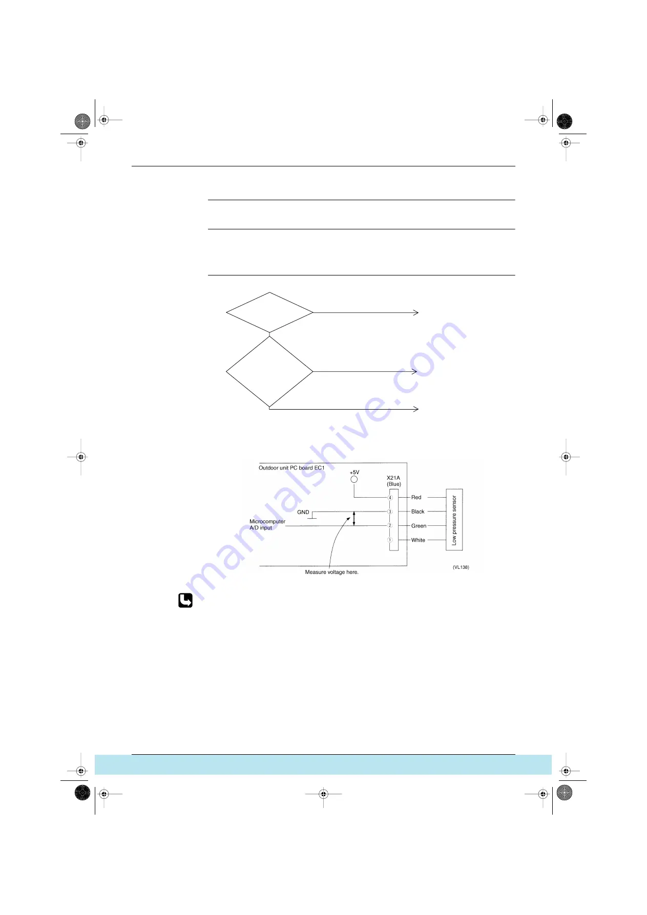
Outdoor Unit: Malfunction of Suction Pipe Pressure Sensor

Remote Controller 
Display

JJJJCCCC

Supposed Causes

Defect of low pressure sensor system

Connection of high pressure sensor with wrong connection. 

Defect of outdoor unit PC board.

Troubleshooting

1: Voltage measurement point

2: Refer to pressure sensor, pressure/voltage characteristics table.

Refer to Pressure Sensor Voltage Output / Detected Pressure Characteristics on P366.

YES

YES

Connection of high pressure 
sensor with wrong 
connection. 

Replace outdoor unit PC 
board A1P.

Replace the low pressure 
sensor. 

The low

pressure sensor is

connected to X21A (blue) of

outdoor unit PC board

(A1P). 

The

relationship

between the 

1

VH and low pressure is

normal (see 

2) when voltage

is measured between X21A pins

(2) and (3) of outdoor unit

PC board (A1P)

(see 

1). 

NO

NO

(VF150)

SI-05C.BOOK  Page 312  Monday, November 6, 2000  4:13 PM

Все каталоги и инструкции здесь:

 http

:

//splitoff.ru/tehn-doc.html

Summary of Contents for VRV Plus Series

Page 1: ... for Restart 28 1 5 Equalized Oil Level Operation Equalized Oil Level between Twin Compressors 30 1 6 Oil Return Operation 31 1 7 Defrost 32 1 8 Heating Pump Down Residual Operation 33 1 9 Step Down Safety Control Standby Forced Thermostat OFF Stop Due to Malfunction 35 1 10 Control During Low Outdoor Air Temperature Cooling 37 1 11 Low Noise Control 39 1 12 Demand Control 40 1 13 Compressor Capac...

Page 2: ...1 21 Schedule Timer DST301A51 DST301B61 108 1 22 Combining Different Types of Centralized Control Devices 112 Part 4 Troubleshooting Inverter K Series 117 1 Operation Flowcharts 119 1 1 Indoor Unit Operation Flowchart 119 1 2 Outdoor Unit Operation Flowchart 124 2 Diagnosis by Malfunction Code 128 2 1 Diagnosis by Malfunction Code 128 2 2 Failure Diagnosis 129 3 Troubleshooting 130 3 1 Indoor Unit...

Page 3: ...n of Transmission Between Master and Slave Remote Controllers 154 3 32 Malfunction of Transmission Between Indoor and Outdoor Units in the Same System 155 3 33 Excessive Number of Indoor Units 156 3 34 Address Duplication of Central Remote Controller 156 3 35 Refrigerant System not set Incompatible Wiring Piping 157 3 36 Malfunction of System Refrigerant System Address Undefined 158 4 Failure Diag...

Page 4: ... Typical Wiring Mistakes 182 Part 5 General Information PLUS Series 189 1 Features of the VRV PLUS Series 190 1 1 Improved Piping System 190 1 2 Improved Piping System 193 1 3 Dramatic Reduction of Wiring Saves Time and Labor When Installing 194 2 System Outline 195 2 1 Heat Pump and Cooling Only System 195 2 2 Heat Recovery System 196 3 Indoor Outdoor Unit Combinations 197 3 1 Indoor Outdoor Unit...

Page 5: ...es 271 1 Test Operation 272 1 1 Procedure and Outline 272 1 2 Operation When Power is Turned On 274 1 3 Outdoor Unit PC Board Ass y 275 1 4 Switch Settings According to Number of Outdoor Units 277 1 5 Setting Modes 278 1 6 Sequential Start 286 1 7 External Control Adaptor for Outdoor Units DTA104A61 DTA104A62 287 1 8 Cool Heat Mode Switching Except for Cooling Only System 290 1 9 Low Noise Operati...

Page 6: ...se Open Phase 315 3 20 Malfunction of Transmission Between Indoor Units 316 3 21 Malfunction of Transmission Between Outdoor Units 317 3 22 Excessive Number of Indoor Units 318 3 23 Refrigerant System not set Incompatible Wiring Piping 319 3 24 Malfunction of System Refrigerant System Address Undefined 320 4 Failure Diagnosis for Inverter System 321 4 1 Points of Diagnosis 321 5 How to Use The Mon...

Page 7: ...1 Thermistor Resistance Temperature Characteristics 364 3 2 Pressure Sensor Voltage Output Detected Pressure Characteristics 366 4 Method of Replacing The Inverter s Power Transistors and Diode Modules 367 4 1 Method of Replacing The Inverter s Power Transistors and Diode Modules 367 5 Wiring Adaptor 369 5 1 Wiring Adaptor for Electrical Appendices KRP2A61 62 369 5 2 Wiring Adaptor for Group Elect...

Page 8: ...SiE 05C viii Table of Contents SI 05C BOOK Page viii Monday November 6 2000 4 13 PM Все каталоги и инструкции здесь http splitoff ru tehn doc html ...

Page 9: ...r Working on the equipment that is connected to a power supply can cause an electrical shook If it is necessary to supply power to the equipment to conduct the repair or inspecting the circuits do not touch any electrically charged sections of the equipment If the refrigerant gas discharges during the repair work do not touch the discharging refrigerant gas The refrigerant gas can cause frostbite ...

Page 10: ...n or fire When relocating the equipment make sure that the new installation site has sufficient strength to withstand the weight of the equipment If the installation site does not have sufficient strength and if the installation work is not conducted securely the equipment can fall and cause injury Be sure to install the product correctly be using the provided standard installation frame Incorrect...

Page 11: ...n from swallowing it If a child swallows the coin battery see a doctor immediately Warning Caution Installation of a leakage breaker is necessary in some cases depending on the conditions of the installation site to prevent electrical shocks Do not install the equipment in a place where there is a possibility of combustible gas leaks If a combustible gas leaks and remains around the unit it can ca...

Page 12: ... the drainage of the indoor unit after the repair Faulty drainage can cause the water to enter the room and wet the furniture and floor Caution Icon Type of Information Description Note Note A note provides information that is not indispensable but may nevertheless be valuable to the reader such as tips and tricks Caution Caution A caution is used when there is danger that the reader through incor...

Page 13: ... fast and reliable after sales service Although the contents of the manual may be insufficient in some areas we hope that you will use it to the best of your ability The service manual for the VRV PLUS Series cool heat selection system explains the new methods super piping and super wiring featured by the system in four sections Outline Functions Test Operation and Troubleshooting Compared with pr...

Page 14: ...Introduction SiE 05C xiv SI 05C BOOK Page xiv Monday November 6 2000 4 13 PM Все каталоги и инструкции здесь http splitoff ru tehn doc html ...

Page 15: ...ATURE 2 1 2 Indoor Outdoor Unit Combinations 4 2 Outline of System 5 2 1 Easily Recognizable Features of the K Series 5 2 2 Changes in K Series Functions Parts 6 2 3 Compatibility of Old and New VRV System Inverter 9 SI 05C BOOK Page 1 Monday November 6 2000 4 13 PM Все каталоги и инструкции здесь http splitoff ru tehn doc html ...

Page 16: ...n SiE 05C 2 General Information Inverter K Series 1 Series Introduction 1 1 NOMENCLATURE 1 1 1 Indoor Unit SI 05C BOOK Page 2 Monday November 6 2000 4 13 PM Все каталоги и инструкции здесь http splitoff ru tehn doc html ...

Page 17: ...ump Doesn t include straight cooling VRV System Inverter Series Capacity Indication 5 5 H P 8 8 H P 10 10 H P Model change symbol Indicates minor design category A B C H For other market J K L Z For EC market Power supply classification Y1 3 380 415V 50Hz YAL 3 380V 60Hz TAL 3 220V 60Hz Special classification E Anti corrosion specs VE002 SI 05C BOOK Page 3 Monday November 6 2000 4 13 PM Все катало...

Page 18: ...ter VRV System Inverter K Series outdoor unit model RSXY5K RSXY8K RSXY10K Total connectable indoor units Max 8 units Max 13 Max 16 RV System Inverter EXC Series outdoor unit model RSX5K RSX8K RSX10K Total connectable indoor units Max 8 units Max 13 Max 16 SI 05C BOOK Page 4 Monday November 6 2000 4 13 PM Все каталоги и инструкции здесь http splitoff ru tehn doc html ...

Page 19: ...verter K Series 5 2 Outline of System 2 1 Easily Recognizable Features of the K Series 2 1 1 VRV System Inverter K Series System Outline Part1 fm Page 5 Wednesday January 31 2001 8 48 AM Все каталоги и инструкции здесь http splitoff ru tehn doc html ...

Page 20: ...es Same terminals used for input and output No polarity 3 wiring methods can be used serial bus and star wiring Up to 16 branches can be used Cannot be branched again once branched System wiring can be up to a total of 2 000 meters Max wiring length up to 1 000 meters Indoor unit terminal block Outdoor unit terminal block 2 central remote controller can be connected in a transmission system VRV Sy...

Page 21: ...or units and setting Simultaneous cool heat selection and low noise operation require a separate adaptor for outside control of outdoor units Transmission can be conducted between a maximum of 10 units Optional controllers for centralized control can be connected to a transmission line between outdoor units VRV System Inverter K Series Outdoor unit F1 F2 F1 F2 Indoor outdoor Outdoor outdoor Indoor...

Page 22: ...he wall mounted type is equipped with a swing louver The ceiling mounted cassette type can be set to prevent the ceiling from being soiled Able to Use Wireless Remote Controllers The multi flow double flow ceiling suspended and wall mounted types can be fitted with a wireless remote controller kit Other types can use a separate wireless remote controller 2 2 3 Changes in Outdoor Units Equipped wit...

Page 23: ...s 1 Old and new indoor units can be used together 2 An Mix Matching Adapter for K Indoor Unit DTA106A61 62 is required for one refrigerant system Can be connected x Cannot be connected Outdoor unit VRV System Inverter K Series RSX RSXY Old indoor unit H Series New indoor unit K Series VL003 DTA106A61 Double flow built in wall mounted concealed floor standing type DTA106A62 Multi flow ceiling suspe...

Page 24: ...Outline of System SiE 05C 10 General Information Inverter K Series SI 05C BOOK Page 10 Monday November 6 2000 4 13 PM Все каталоги и инструкции здесь http splitoff ru tehn doc html ...

Page 25: ... Down Residual Operation 33 1 9 Step Down Safety Control Standby Forced Thermostat OFF Stop Due to Malfunction 35 1 10 Control During Low Outdoor Air Temperature Cooling 37 1 11 Low Noise Control 39 1 12 Demand Control 40 1 13 Compressor Capacity Control 41 1 14 Te Tc Setting 43 1 15 Gas Depletion Alarm 44 1 16 Drain Pump Control 45 1 17 Oil Temperature Sensor 8 and 10 Hp only 47 1 18 Louver Contr...

Page 26: ...nt System Diagram RSX5K Series Products produced before July 99 and included RSX5KY1C model produced before Dec 99 Note 1 These check valves are not fitted for RSX5KY1C model SI 05C BOOK Page 12 Monday November 6 2000 4 13 PM Все каталоги и инструкции здесь http splitoff ru tehn doc html ...

Page 27: ...oad when the compressor starts D Outdoor unit electronic expansion valve Y1E Expansion valve is kept open E Solenoid valve injection Y3S Controls injection in order to prevent overheating F Heat exchange pipe Subcools so that refrigerant drift doesn t occur between indoor units when flash gas is produced in the liquid pipe G Pressure sensor high pressure red SENPH Semiconductor pressure sensor car...

Page 28: ...Note 1 These check valves are not fitted for RSXY5KY1C model 2 These check valves are not fitted for products produced after Aug 99 and RSXY5KY1C model produced after Jan 2000 SI 05C BOOK Page 14 Monday November 6 2000 4 13 PM Все каталоги и инструкции здесь http splitoff ru tehn doc html ...

Page 29: ...sion valve Y1E Expansion valve when heating Senses compressor suction pipe and low pressure equivalent saturated temperature and carries out superheat degree control E Solenoid valve injection Y3S Controls injection in order to prevent overheating F Heat exchange pipe Subcools so that refrigerant drift doesn t occur between indoor units when flash gas is produced in the liquid pipe G Pressure sens...

Page 30: ...rter K Series RSX5K Series Products produced after August 99 RSX5KY1C model produced after Jan 2000 DU229 622A SENPL SENPH SI 05C BOOK Page 16 Monday November 6 2000 4 13 PM Все каталоги и инструкции здесь http splitoff ru tehn doc html ...

Page 31: ...pressure when off in order to reduce load when the compressor starts E Solenoid valve injection Y3S Controls injection in order to prevent overheating F Heat exchange pipe Subcools so that refrigerant drift doesn t occur between indoor units when flash gas is produced in the liquid pipe G Pressure sensor high pressure red SENPH Semiconductor pressure sensor carries out heat exchange control during...

Page 32: ...Products produced before July 99 and Included RSX8K 10KY1C models produced before Dec 99 Note 1 These check valves are not fitted for RSX8K 10KY1C models SI 05C BOOK Page 18 Monday November 6 2000 4 13 PM Все каталоги и инструкции здесь http splitoff ru tehn doc html ...

Page 33: ...sor The collected oil is constantly recycled to the compressor via capillary tube E Solenoid valve hot gas bypass Y2S Valve is opened by low pressure safety control when low pressure drops F Outdoor unit electronic expansion valve Y1E Expansion valve is kept open G Solenoid valve injection Y3S Y4S Controls injection in order to prevent overheating Y3S Inverter compressor Y4S Standard compressor H ...

Page 34: ...roducts produced before July 99 and Included RSXY8K 10KY1C models produced before Dec 99 Note 1 These check valves are not fitted for RSXY8K 10KY1C models SI 05C BOOK Page 20 Monday November 6 2000 4 13 PM Все каталоги и инструкции здесь http splitoff ru tehn doc html ...

Page 35: ... via capillary tube E Solenoid valve hot gas bypass Y2S Valve is opened by low pressure safety control when low pressure drops F Outdoor unit electronic expansion valve Y1E Expansion valve when heating Senses compressor suction pipe and low pressure equivalent saturated temperature and carries out superheat degree control G Solenoid valve injection Y3S Y4S Controls injection in order to prevent ov...

Page 36: ...eries RSX8 10K Series Products produced after August 99 RSX8K 10KY1C models produced after Jan 2000 SENPL INV STD SENPH DU232 607A SI 05C BOOK Page 22 Monday November 6 2000 4 13 PM Все каталоги и инструкции здесь http splitoff ru tehn doc html ...

Page 37: ...r The collected oil is constantly recycled to the compressor via capillary tube E Solenoid valve hot gas bypass Y2S Valve is opened by low pressure safety control when low pressure drops Balances high low pressure when off in order to reduce load when the compressor starts G Solenoid valve injection Y3S Y4S Controls injection in order to prevent overheating Y3S Inverter compressor Y4S Standard com...

Page 38: ...eries RSXY8K 10K Series Products produced after August 99 RSXY8K 10KY1C models produced after Jan 2000 4D014597 SENPL INV STD SENPH SI 05C BOOK Page 24 Monday November 6 2000 4 13 PM Все каталоги и инструкции здесь http splitoff ru tehn doc html ...

Page 39: ...t gas bypass Y2S Valve is opened by low pressure safety control when low pressure drops Balances high low pressure when off in order to reduce load when the compressor starts F Outdoor unit electronic expansion valve Y1E Expansion valve when heating Senses compressor suction pipe and low pressure equivalent saturated temperature and carries out superheat degree control G Solenoid valve injection Y...

Page 40: ...6 Functions Inverter K Series 1 2 Function of Thermistors and Pressure Sensors 1 2 1 Outdoor Unit RSXY8 10K SI 05C BOOK Page 26 Monday November 6 2000 4 13 PM Все каталоги и инструкции здесь http splitoff ru tehn doc html ...

Page 41: ... 0 1 0kg cm ON 20 0 1 0 1 0kg cm S1HP Pressure switch for high pressure safety 20SP 688 6 OFF 27 5 0 1 0kg cm2 ON 20 0 1 0 1 0kg cm S2HP Pressure switch for high pressure safety 20SP 688 6 OFF 27 5 0 1 0kg cm2 ON 20 0 1 0 1 0kg cm Fusible plug FPG 3D 70 75 C Sensor SENPH Pressure sensor PS8030A 0 30kg cm 0 2 94MPa SENPL Pressure sensor PS8030A 0 10kg cm 0 0 98MPa R1T Thermistor for outdoor air 3 5...

Page 42: ...indoor unit s electronic expansion valve for 5 minutes 10 minutes for 8 and 10HP 1 4 2 Soft Start The following control is carried out to protect the compressor and inverter 1 Operates at low frequency fixed for 1 minute after compressor starts Prevents liquid refrigerant backflow 2 Pressure equalizing and hot gas bypass solenoid valves open and start low load Soft Start of Compressor Thermostat T...

Page 43: ...too low in the following cases When after being power ON the accumulated running time of the compressor does not exceed one hour When the compressor has been stopped for more than 24 hours Operation During Heating Lay Up Start Make the compressor s upper limit frequency 60Hz 60Hz OFF for 10 minutes 20 seconds after the compressor starts If the low pressure becomes 1 5kg cm 0 147MPa within 10 minut...

Page 44: ...ure inside the dome due to drift and then reverts to normal operation If oil pressure equalization is not achieved during 5 minutes by stopping or step down control oil pressure equalization is carried out when the compressor starts running With an inverter compressor operation however if the standard compressor remains off for 10 minutes the cumulative running time of the standard compressor is r...

Page 45: ...e 16kg cm 1 57MPa Step 2 Step 3 High pressure 7 5 kg cm 0 74MPa Step 3 Step 2 High pressure 15 kg cm 1 47MPa Step 2 Step 1 High pressure 20 kg cm 1 96MPa When heating only On when low pressure 0 3 kg cm 0 029MPa Off when low pressure 0 8 kg cm 0 078MPa Notes 1 If the compressor frequency continues at 68Hz 38Hz ON for 8 10HP or more for more than eight minutes with defrosting while the oil return t...

Page 46: ...n M Defrost is carried out when the coil temperature rises to 12 5ºC or higher and is completed after defrosting for 10 minutes After defrosting indoor units carry out hot start operation and the DEFROSTING display lights until hot start is complete Defrost conditions are not counted from completion of power supply set up and defrost until the compressor runs count for 20 minutes Tcoil C Tair α Tc...

Page 47: ...ed out if the total of 1 2 3 is 10 minutes or more 3 When outdoor temperature R1T 5 C and a stop command is received from the thermostat sensor etc residual operation is carried out for 10 minutes without fail Operation may however stop for discharge pipe or high low pressure safety Discharge pipe thermistor R3 1T on inverter side 95 C or lower OR Outside air temperature thermistor R1T 0 C When co...

Page 48: ... even if a stop command comes Forced thermostat OFF occurs if defrost or oil return signal comes during residual operation Outdoor air R1T Compressor Electronic expansion valve Pressure equalizing solenoid valve Time INV STD R1T 10 C 86Hz OFF 0 300 pulses ON or OFF 10 min 10 C R1T 0 C 76Hz OFF 0 300 pulses ON or OFF 10 min R1T 0 C 60Hz OFF 0 300 pulses ON or OFF 10 min SI 05C BOOK Page 34 Monday N...

Page 49: ... valve ON Lp 0 8kg cm 0 078MPa 54 Hz OFF 54Hz as lower limit Forced OFF by thermostat Up to 2 times in 30 minutes E4 stop due to malfunction Hot gas bypass valve ON VF002 Td 135 C Td 105 C or DSH 55 C DSH Discharge Super Heating or Td 90 C Lp 3kg cm Control during cooling or 0 294MPa Td 90 C Lp 2kg cm Control during heating 0 196MPa FREQUENCY 1 3 STEP DOWN Td 135 C Forced thermostat OFF Up to 2 ti...

Page 50: ...inverter standard compressor are controlled at 76 Hz or less OFF for 3 minutes Control According to Outdoor Temperature If the outdoor temperature exceeds 27 C when heating forced thermostat OFF is carried out in order to prevent a safety device from being tripped or a sensor malfunction INV 27 0A TAL 15 0A Y1 YAL FREQUENCY 1 STEP DOWN L8 stop due to malfunction 27 0 15 0 INV 27 5A TAL 15 0A Y1 YA...

Page 51: ... Step 1 Fully open L 76 Step 2 Fully open OFF 48 Operating status Electronic expansion valve Fan Frequency Hz M1F M2F 8K 10K Normal operation Fully open H ON Changes according to operating status Low outdoor temperature cooling operation Step 1 1 Fully open L ON 96 116 Step 1 2 Fully open H OFF 86 106 Step 1 3 Fully open L OFF 76 96 Step 2 Fully open OFF OFF 60 76 Normal operation Step 1 1 Step 1 ...

Page 52: ...ure 15 8 kg cm 1 548 MPa or Outdoor air temperature 25 C or Radiator fin temperature 80 C Condition satisfied Conditions satisfied VF007 1 Normal operation Step 2 Cooling with compressor running doesn t include oil return High pressure 7 5 kg cm 0 735 MPa Radiator fin temperature 60 C Compressor off or Other than cooling includes oil return or High pressure 15 8 kg cm 1 548 MPa or Radiator fin tem...

Page 53: ... 1 86 MPa Low noise control reduces capacity by limiting the fan and compressor The load when heating is particularly large at night when the outdoor temperature is low and could result in insufficient capacity During low noise control retry is unlimited for standby forced thermostat OFF produced by high pressure low pressure or discharge pipe temperature An optional external control adaptor of ou...

Page 54: ...optional external control adaptor of outdoor units is required for demand control For method of connection see demand operation in the test operation section Control is carried out by limiting the upper limit for frequency of demand 1 and demand 2 as given in the table below For products produced after Aug 99 5HP 8HP 10HP Demand 1 68Hz 48Hz ON 60Hz ON Demand 2 34Hz 60Hz OFF 76Hz OFF Demand 3 Force...

Page 55: ...controlled in 21 stages by microcomputer 20 Stages for products produced after Aug 99 Frequency 30Hz 34Hz 38Hz 42Hz 48Hz 54Hz 60Hz 68Hz 76Hz 86Hz 96Hz 106Hz 116Hz Min output Max output VE004 Commercial power supply compressor off Frequency 30Hz OFF 34Hz OFF 38Hz OFF 42Hz OFF 48Hz OFF 54Hz OFF 60Hz OFF 68Hz OFF 76Hz OFF 86Hz OFF 96Hz OFF 106Hz OFF 116Hz OFF Commercial power supply compressor full l...

Page 56: ...38Hz OFF 42Hz OFF 48Hz OFF 54Hz OFF 60Hz OFF 68Hz OFF 76Hz OFF 86Hz OFF 96Hz OFF 106Hz OFF Commercial power supply compressor full load Frequency 38Hz ON 48Hz ON 60Hz ON 76Hz ON 86Hz ON 96Hz ON 106Hz ON 116Hz ON Min output Max output VE006 SI 05C BOOK Page 42 Monday November 6 2000 4 13 PM Все каталоги и инструкции здесь http splitoff ru tehn doc html ...

Page 57: ...ad The range is 10 C target Te 5 5 C Piping length is determined automatically during oil return operation Target Tc becomes 3 C higher when indoor load is large Target Tc is controlled in accordance with the following conditions Outdoor temp 10 C target Tc 46 C Outdoor temp 10 C target Tc 49 C Target Tc 43 C when high pressure 17 kg cm 1 67 MPa and low pressure 1 8 kg cm 0 176 MPa Te setting Set ...

Page 58: ... While compressor is running and 4 way valve ON heating cycle and Evaporator outlet superheat temperature 20 C difference and Outdoor unit electronic expansion valve 2000 pulses completely open Gas depletion alarm cancellation Gas depletion alarm U0 is displayed Conditions given on the left continue for 60 min Compressor off or 4 way valve OFF cooling cycle defrost or Evaporator outlet superheat t...

Page 59: ...ive of residual operation is to completely drain any moisture adhering to the fin of the indoor unit heat exchanger when the thermostat goes off during cooling operation 2 One cycle consists of 5 minutes of operation 5 seconds stop and another 5 minutes of operation 1 16 2 When the Float Switch is Tripped During Cooling OFF by Thermostat SI 05C BOOK Page 45 Monday November 6 2000 4 13 PM Все катал...

Page 60: ...nutes operation cycle ends operation continues until the switch is reset 1 16 4 When the Float Switch is Tripped and AF is Displayed on the Remote Controller Note If the float switch is tripped five times in succession a drain malfunction is determined to have occurred AF is then displayed as operation continues SI 05C BOOK Page 46 Monday November 6 2000 4 13 PM Все каталоги и инструкции здесь htt...

Page 61: ...l temperature sensor For products produced after Aug 99 The unit controls upper limit frequency of the compressor and is designed to prevent oil from being diluted while defrosting by means of an oil temperature sensor Startup subsequent to defrosting is improved by the oil temperature sensor R5T Te 10 C SH 10 C R5T Te 10 C SH 5 C VF010 R5T Te 10 C INV 86Hz STD ON R5T Te 10 C INV 116Hz STD ON VF01...

Page 62: ...0 P1 P2 P4 P3 P0 P0 P1 P2 P4 P4 P2 P1 P0 P4 P4 P3 P2 P1 P0 P3 Existing position Draft prevention position Standard Setting position Ceiling soiling prevention position Draft prevention position Standard position Prohibited Prohibited Dirt prevention position P0 P0 P0 P1 P2 P2 P1 P3 P3 P4 P4 P1 P P3 P4 Same as existing position Separated into 5 positions P1 4 Separated into 5 positions P2 4 Range o...

Page 63: ...ure in the figure above is 24 C and the suction temperature has changed from 18 C to 30 C A F This example also assumes there are several other air conditioners the VRV system is off and that temperature changes even when the thermostat sensor is off Body thermostat sensor is used for temperatures from 18 C to 23 C A C Remote controller thermostat sensor is used for temperatures from 23 C to 27 C ...

Page 64: ...reset temperature Ex When heating Assuming the preset temperature in the figure above is 24 C and the suction temperature has changed from 18 C to 28 C A F This example also assumes there are several other air conditioners the VRV system is off and that temperature changes even when the thermostat sensor is off Body thermostat sensor is used for temperatures from 18 C to 25 C A C Remote controller...

Page 65: ...th the following conditions and is also set in accordance with the conditions given below Conditions for starting freeze prevention Temperature is 1 C or less for total of 40 min or temperature is 5 C or less for total of 10 min Conditions for stopping freeze prevention Temperature is 7 C or more for 10 min continuously Ex Case where temperature is 5 C or less for total of 10 min SI 05C BOOK Page ...

Page 66: ...Functions SiE 05C 52 Functions Inverter K Series SI 05C BOOK Page 52 Monday November 6 2000 4 13 PM Все каталоги и инструкции здесь http splitoff ru tehn doc html ...

Page 67: ...lers Group Remote 81 1 12 Indoor Field Setting 83 1 13 Centralized Control Group No Setting 85 1 14 Setting of Master Remote Controller 87 1 15 Remote Controller Self Diagnosis Function 89 1 16 Operation of the Remote Controller s Inspection Test Operation Button 92 1 17 Remote Controller Service Mode 93 1 18 Model Change of Centralized Control Devices 95 1 19 Central Remote Controller DCS302A51 D...

Page 68: ...t automatically Outdoor unit HWL lamp On Test lamp H2P Flicker Can be set while in operation Indoor unit If the ON OFF button is pushed during the aforementioned operation the operation lamp lights but the unit will not run Returns to normal when automatic setting is complete 1 1 3 If outdoor indoor or BS unit is extended or if indoor outdoor unit PC board is replaced In these cases be sure to pus...

Page 69: ... Test Operation Test Operation Inverter K Series 55 1 2 Outdoor Unit PC Board Ass y RSXY8K 10K SI 05C BOOK Page 55 Monday November 6 2000 4 13 PM Все каталоги и инструкции здесь http splitoff ru tehn doc html ...

Page 70: ...check Reset button Push and hold for 5 sec if the indoor unit s PC board has been replaced or there has been a change in the combination of indoor and outdoor units such as indoor unit extension etc 3 Jumper pin Forced defrost operation by short circuit Setting mode 1 H1P off Push 1 time Monitor mode H1P flickers Push 1 time Push and hold for 5 sec Setting mode 2 H1P on Push 1 time VF014 BLAUW M D...

Page 71: ...tting mode 1 You don t have to perform power supply reset after changing settings in setting mode 1 including SS1 cool heat selection switch on the outdoor unit PC board and setting mode 2 Push the MODE button Push the MODE button Push the SET button Push and hold the MODE button for 5 sec Push the MODE button Setting mode 1 Initial setting Set Push the RETURN button Push the RETURN button Push th...

Page 72: ...ON low noise OFF sequential start MODE TEST L N O P SEQ IND MASTER SLAVE START H1P H2P H3P H4P H5P H6P H7P SET MODE TEST L N O P SEQ IND MASTER SLAVE START H1P H2P H3P H4P H5P H6P H7P C H SELECT SET MODE TEST L N O P SEQ IND MASTER SLAVE START H1P H2P H3P H4P H5P H6P H7P C H SELECT MODE TEST L N O P SEQ IND MASTER SLAVE START H1P H2P H3P H4P H5P H6P H7P C H SELECT SET SET MODE TEST L N O P SEQ IND...

Page 73: ...ress Low noise demand address Forced fan switch Indoor unit forced operation Frequency fix Te setting Tc setting Defrost setting Not used Description Emergency operation when malfunction occurs Address for cool heat group operation Address for low noise demand group operation Fan of stopped indoor unit turns Allows operation of indoor unit from outdoor unit Fixes the frequency of the inverter comp...

Page 74: ...uency fix Normal operation Fixes the frequency of the inverter compressor 5HP 68Hz 8 10HP 86Hz ON Frequency fix 6 S Address 0 Binary number 1 6 digits 2 31 Address for cool heat group operation Cool heat group address 2 S S S S Address 0 Binary number 1 6 digits 2 63 Airnet address Not used 10 S S S S Address 0 Binary number 1 6 digits 2 31 Address for low noise demand group operation Low noise de...

Page 75: ...tting for defrost Quick defrost Normal factory set Slow defrost EMG emergency operation when malfunction occurs ON OF Push the SET button and match with the LEDs No 1 15 push the RETURN button and enter the data for each setting Data such as addresses and number of units is expressed as binary numbers the two ways of expressing are as follows See the following page for a list of the data for No 1 ...

Page 76: ...ted zone units excluding outdoor and BS units 0 63 units Lower 6 digits No 8 Number of outdoor units 0 63 units Lower 6 digits No 9 Number of BS units 0 128 units Lower 4 digits upper No 10 Number of BS units 0 128 units Lower 4 digits lower No 11 Number of zone units excluding outdoor and BS units 0 63 units Lower 6 digits No 12 Number of terminal blocks 0 128 units Lower 4 digits upper No 13 Num...

Page 77: ...the third unit in the sequence Method of Sequential Start 1 Power supply wiring Must be wired as a group to the power supply 2 Wiring Connect transmission wiring to terminals F1 and F2 outdoor outdoor on the outdoor unit PC board A1P Switch to the monitoring mode and see if sequential start has been selected If not switch to setting mode 1 and select sequential start Sequential start is factory se...

Page 78: ... Function switch SS1 Factory set BOTH Sets whether the address setting switch will set cool heat address demand low noise address or both 4 Cool heat central remote controller selection switch SS2 Factory set No Sets whether cool heat central remote controller is connected or not 5 Address setting switch DS2 DS1 Factory set 0 Sets cool heat address or demand address The black part represents the s...

Page 79: ...ndoor unit remote controller Switch Settings on the Adaptor PCB SS1 SS2 DS1 DS2 BOTH C H DE FUNCTION BOTH BOTH C H DE FUNCTION C H OR VL021 CENTRAL C H SELECTOR OFF ON OFF VL022 DS2 DS1 Address 0 VL023 SI 05C BOOK Page 65 Monday November 6 2000 4 13 PM Все каталоги и инструкции здесь http splitoff ru tehn doc html ...

Page 80: ... Setting mode 2 Cool heat group address 0 Combines DS1 and DS2 of PC board adaptor Group slave unit SS1 IN D UNIT or OUT D UNIT Setting mode 1 C H SELECT SLAVE Setting mode 2 Cool heat group address 0 Combines DS1 and DS2 of adaptor PCB SI 05C BOOK Page 66 Monday November 6 2000 4 13 PM Все каталоги и инструкции здесь http splitoff ru tehn doc html ...

Page 81: ...ote controller 4 Setting of cool heat by outdoor unit system group in accordance with group master outdoor unit by cool heat selector Each of these setting methods is explained in detail below For 3 and 4 be sure to perform power supply reset after changing settings 1 6 1 Setting of Cool Heat by Individual Outdoor Unit System by Indoor Unit Remote Controller Doesn t matter whether or not there is ...

Page 82: ...tem by Cool Heat Selector Doesn t matter whether or not there is outdoor outdoor unit wiring Set SS1 of the outdoor unit PC board to OUT D UNIT In setting mode 1 set cool heat selection to IND factory set SI 05C BOOK Page 68 Monday November 6 2000 4 13 PM Все каталоги и инструкции здесь http splitoff ru tehn doc html ...

Page 83: ...nt to give cool heat selection permission to as the group master and set the other outdoor units as group slave units Set SS1 of the External control adaptor for outdoor unit to BOTH factory set or C H Set SS2 to OFF factory set 1 6 4 Setting of Cool Heat by Outdoor Unit System Group in Accordance with Group Master Outdoor Unit by Cool Heat Selector In addition to 1 6 3 change the following Instal...

Page 84: ...door unit group slave No 0 Outdoor unit group slave No 0 Cool heat group address DS2 DS1 Adaptor PCB No 1 Outdoor unit group master No 1 Outdoor unit group slave No 1 Cool heat group address DS2 DS1 Adapter PCB No 2 Outdoor unit group master No 2 Outdoor unit group slave No 2 Outdoor unit group slave No 2 Cool heat group address DS2 DS1 Adapter PCB No 3 Outdoor unit group master No 3 Outdoor unit ...

Page 85: ...ation Inverter K Series 71 Setting Method 1 6 3 and 1 6 4 address setting method combine lower 5 digits as binary number SI 05C BOOK Page 71 Monday November 6 2000 4 13 PM Все каталоги и инструкции здесь http splitoff ru tehn doc html ...

Page 86: ...ch zone Outdoor unit address setting Setting mode 2 see page 59 External control adaptor for outdoor unit address setting Decide and set demand address 0 31 for each demand and low noise control zone See fig below Set SS1 to BOTH factory set or C H F1 F2 Demand address F1 F2 External control adaptor for outdoor unit F1 F2 F1 F2 DS2 DS1 No 0 F1 F2 F1 F2 Demand address F1 F2 External control adaptor...

Page 87: ...ox 40 Short circuit between Demand 3 and C Forced OFF by thermostat L N O jumper Carries out low noise operation Input Signal Input current by constant contact a is about 10 mA per contact Use a micro current contact for the relay contact Exterior wiring specifications for demand and low noise operation Recommended wiring Sheathed vinyl cord or cable Wiring length 150 m Keep away from power line i...

Page 88: ...es off when finished If TEST H2P flickers wiring check operation failure push and hold the RESET button BS5 for 5 seconds and then repeat the procedure from the beginning 3 About 1 minute after you finish running the system once again check the number of connected indoor units in the monitor mode and make sure the number agrees with the first time you checked If not it indicates that there is a wi...

Page 89: ...unction status of the microcomputer Normal Flicker Malfunction On or off 2 Transmission wiring terminal Terminal for remote controller wiring indoor outdoor unit transmission wiring central wiring and wiring for outside input Remote controller Transmission wiring Outside input N P F1 F2 T1 T2 3 Connector for capacity setting adaptor Connector for inserting the capacity setting adaptor for when rep...

Page 90: ...l heat exchanger units Applies only to B Series and multifunctional types Display of malfunction is also available for air cleaner units Operation can be individually programmed to start and stop time up to 72 hours in advance The remote controller is equipped with a thermostat sensor to realize better room temperature control Room temperature and preset temperature are monitored by microcomputer ...

Page 91: ...ote controller wiring can be extended up to 500 meters and you can easily make a central control setup in one place with indoor unit remote controllers set up in various places around the room Interlock control You can simultaneously control HRV total heat exchanger units or humidifiers with direct expansion coils via an indoor unit Also displays cleaning period for air cleaner units System extens...

Page 92: ...alized control 6 Timer ON OFF button 18 ON OFF button Push to turn the timer on or off One push starts the system and a second push stops the system again 7 Inspection test operation button 19 Operation lamp Red Push for inspection or test operation Lights during operation 8 Programming time button 20 Display changeover under control Push to set programming time Cool heat auto dry cannot be be swi...

Page 93: ...imer on or off 4 Display air flow flap 13 Programming time button Displays fixed or swing for air direction Push to set programming time 5 Inspection test operation display 14 Time mode START STOP button When the inspection test operation button is pushed displays whether the system is in the inspection or test operation mode Push to start or stop the timer 6 Fan speed adjustment button 15 ON OFF ...

Page 94: ... flow direction is set by adjusting with the air flow direction adjustment button while viewing setting position in the liquid crystal display The air flow direction is set by adjusting with the air flow direction adjustment button while viewing the position of the louver Filter sign reset Resets the filter and element cleaning display Resets the filter and element cleaning display Displayed by op...

Page 95: ...trollers front panels and set the MASTER SLAVE switch on the remote controller s built in PC board to MASTER for the master remote controller and SLAVE for the slave remote controller Field setting can be made only for the master remote controller Group Control Up to 16 indoor units are sinaltaneously controlled as a group with single remote controller System which is convenient for cases where fo...

Page 96: ...input by remote controller after turning on the power supply Set field setting mode with the remote controller When you enter the field setting mode select mode No 12 and set the first code No to 1 for forced OFF set the second code No to 01 and from ON OFF control set to 02 Factory set is forced OFF Wiring specifications Sheathed vinyl cord or cable double core Wiring thickness 0 75 1 25mm Wiring...

Page 97: ...e mode button and select the indoor unit No to be set Note This operation is not required when setting as a group 4 Push the button and select the first code No 5 Push the button and select the second code No 6 Push the timer button one time and define the currently set contents 7 Push the button to return to the normal mode 1 12 2 Wireless Remote Controller 1 When in the normal mode push the butt...

Page 98: ...an air filter calculation Set when filter sign is not to be displayed Display No display 12 22 0 Optional accessories output selection field selection of output for adaptor for wiring Indoor unit turned ON by thermostat Operation output Malfunctionoutput 1 ON OFF input from outside Set when ON OFF is to be controlled from outside Forced OFF ON OFF control External protection device 2 Thermostat di...

Page 99: ...for each group with the button The group No increases in the manner of 1 00 1 01 1 15 2 00 4 15 However the unified ON OFF controller displays only the group No within the range selected by the switch for setting each address 5 Push the timer button to define the selected group No 6 Push the button to return to the normal mode Even if not using a remote controller connect the remote controller whe...

Page 100: ...set mode 2 Set mode No 00 with button 3 Set the group No for each group with button advance backward 4 Enter the selected group numbers by pushing button 5 Push button and return to the normal mode Group No Setting Example If you have to set the address for each unit for calculating cost etc set the mode No to 30 SI 05C BOOK Page 86 Monday November 6 2000 4 13 PM Все каталоги и инструкции здесь ht...

Page 101: ... outdoor unit s cool heat selector Filed setting mode1 to inside 2 Continue pushing OPERATION MODE SELECTOR for about 4 seconds The display of CHANGEOVER UNDER CONTROL on all remote controllers connected to the same outdoor unit blinks 3 Push the OPERATION MODE SELECTOR of the remote controller you want to set as the master remote controller This completes the setting The remote controller is now ...

Page 102: ...OL HEAT l switch to the operation mode set by the master remote controller l However they can switch to FAN operation and from COOL to If you set a Master remote controller Remote controller not displaying CHANGEOVER UNDER CONTROL The other remote controllers Remote controllers displaying CHANGEOVER UNDER CONTROL 2 to FAN l cannot set any mode other than FAN VL049 SI 05C BOOK Page 88 Monday Novemb...

Page 103: ...ndoor unit Malfunction of thermistor R3T for gas pipes loose connection disconnection short circuit failure Blinking Blinking Blinking C9 Indoor unit Malfunction of thermistor R1T for air inlet loose connection disconnection short circuit failure On On On CJ Indoor unit Malfunction of thermostat sensor in remote controller Blinking Blinking Blinking E0 Outdoor unit Actuation of safety device Blink...

Page 104: ...se Blinking Blinking Blinking U2 Power supply insufficient or instantaneous failure Blinking Blinking Blinking U4 Malfunction of transmission between indoor unit and outdoor unit BS unit or outdoor unit and BS unit Blinking Blinking Blinking U5 Malfunction of transmission between remote controller and indoor unit Off On Off U5 Failure of remote controller PC board or setting during control by remo...

Page 105: ...cate the upper code 5 Push the operation mode selector button and the lower digit of the malfunction code blinks 6 Push the time mode button until signal reception beeps continuously and then locate the lower code Continuous signal reception beep indicates that the malfunction code has been ascertained Note 1 INSPECTION display blinks when the remote controller s button is pushed 2 If you push and...

Page 106: ...XYH FXYS FXYL FXYM Type VRV System Inverter K Series Other models VRV System Display A A 1 Outdoor model code Model RSXY Unit Malfunction code Inspection Normal display No display 0 L 0 Malfunction code blinks when a malfunction occurs Unit Malfunction code Inspection Inspection mode Push the button Inspection test operation Push the button Inspection test operation Push the button Inspection test...

Page 107: ...No For group control only Select the indoor unit No to be set with the time mode button 3 Make the settings required for each mode Modes 41 44 45 For details refer to the table below 4 Define the setting contents Modes 44 45 Define by pushing the timer button 5 Return to the normal operation mode Push the button one time SI 05C BOOK Page 93 Monday November 6 2000 4 13 PM Все каталоги и инструкции ...

Page 108: ...utton you can turn the fan of each indoor unit on forced ON individually 4 4 4 44 4 4 4 Individual setting Set the fan speed and air flow direction by each unit Select the unit No with the time mode button Set the fan speed with the button Set the air flow direction with the button 4 4 4 45 5 5 5 Unit No transfer Transfer unit No Select the unit No with the button Set the unit No after transfer wi...

Page 109: ...r Model No DCS302A51 DCS302B61 Appearance Outside dimensions and operation functions are the same No of units that can be connected within one control wiring system 1 Up to 2 Unified ON OFF controller Model No DCS301A51 DCS301B61 Appearance Outside dimensions and operation functions are the same No of units that can be connected within one control wiring system Up to 4 Up to 8 Schedule timer Model...

Page 110: ...ol by remote controller is required if more than 64 units are connected with the same system Only 1 central remote controller can be connected per system Up to 4 unified ON OFF controllers can be connected per system Only 1 schedule timer can be connected per system SI 05C BOOK Page 96 Monday November 6 2000 4 13 PM Все каталоги и инструкции здесь http splitoff ru tehn doc html ...

Page 111: ...nnected within the system When double remote controllers are connected the same indoor unit cannot be registered for more than one central remote controller Up to 2 central remote controllers can be connected per system Up to 8 unified ON OFF controllers can be connected per system Only 1 schedule timer can be connected per system SI 05C BOOK Page 97 Monday November 6 2000 4 13 PM Все каталоги и и...

Page 112: ...ion with other D BACS equipment and allows input from outside of forced OFF etc Enables individual on off and monitoring of total heat exchanger units HRV model B Series and multifunction type 1 19 1 System Configuration With a central remote controller you can simultaneously turn up to 64 groups of indoor units on or off up to 128 units You can also turn on or off set operation and control modes ...

Page 113: ...e groups Zone control lets you make settings for several groups simultaneously in order to facilitate the task of setting By setting once everything in the zone becomes set to the same setting The number of zones that can be set by the central remote controller is MINI MAX 64 zones The number of groups in 1 zone is MINI MAX 64 groups The manner of linking zones can be set as desired with the centr...

Page 114: ...tc in code If there is an indoor unit stopped due to malfunction the display indicates that unit s unit No 5 Group No in operation 14 Unified stop button Each square displays the state corresponding to each group Stops all indoor units 6 Display preset temperature 15 Unified operation button Displays the preset temperature Runs all indoor units 7 Display inspection test 16 Operation lamp Press the...

Page 115: ...tton Selects zone or group display Defines control mode and timer No 5 Advance backward button 13 Control mode button Sets zone with several groups Selects the control mode 6 ON OFF button 14 Timer No button Runs or stops for each zone Selects timer No Only when used in combination with a schedule timer 7 Temperature setting button 15 Zone operation ON OFF button Push to set temperature Defines zo...

Page 116: ...Star wiring can be branched in max 16 locations Example showing 3 branches Notes 1 Cannot be branched again after being branched once 2 Use a junction terminal block if branching 3 or more control wires from the same terminal block 3 Do not connect transmission wiring between indoor and outdoor units of different refrigerant circuits SI 05C BOOK Page 102 Monday November 6 2000 4 13 PM Все каталоги...

Page 117: ...FF control impossible by remote controller Used when you want to turn on off by central remote controller only Cannot be turned on off by remote controller OFF control only possible by remote controller Used when you want to turn on by central remote controller only and off by remote controller only Centralized Used when you want to turn on by central remote controller only and turn on off freely ...

Page 118: ...ature control Operation mode setting Unified operation individual operation by central remote controller or operation controlled by timer Unified OFF individual stop by central remote controller or timer stop ON OFF control impossible by remote controller Rejection Example Rejection Example Rejection Example Rejection Acceptance 0 Rejection 10 Acceptance Example Acceptance Example 1 Example Reject...

Page 119: ...atures compact size casing with thickness of only 16 mm Uses JIS recessed box for 2 Wiring can be extended up to 1 km For the wiring method bus type and star type wiring crossover wiring can be used as well as crossover wiring Can be used in combination with other D BACS equipment 1 20 1 System Configuration Up to 16 groups of indoor units can be turned on off individually or simultaneously by uni...

Page 120: ... 2 remote controllers 1 20 2 Wiring for Transmission Wiring Outline Wiring specifications Connection Example of Wiring for Transmission 1 series wiring 2 bus type wiring and 3 star type wiring are the same as with a central remote controller Power supply wiring 2 mm Wiring for transmission 0 75 1 25 mm sheathed vinyl cord or cable double core max extension 1000 m total wiring length 2000 m Power s...

Page 121: ... F2 are inverted 1 Forced OFF input T1 T2 All connected indoor units go off and do not run while forced OFF input for no voltage contact micro current is closed Use a contact that can guarantee a 16 VDC 10 mA minimum applicable load NOTE If using an instantaneous contactor use one that handles conducting time of 200 msec or more 2 Power supply for schedule timer D1 D2 Wire only if 1 2 and 3 are us...

Page 122: ...ed Equipped with a power failure compensation function effective for up to 48 hours Features compact size casing with thickness of only 16 mm Uses JIS recessed box for 2 Wiring can be extended up to 1 km For the wiring method bus type and star type wiring crossover wiring can be used as well as crossover wiring Can be used in combination with other D BACS equipment 1 21 1 System Configuration and ...

Page 123: ...and crimp style terminals 2 If using in combination with other optional controllers for centralized control Wiring for transmission 0 75 1 25 mm sheathed vinyl cord or cable double core Max extension 1000 m Total wiring length 2000 m Connection example of wiring for transmission 1 series wiring 2 bus type wiring and 3 star type wiring are the same as with a central remote controller SI 05C BOOK Pa...

Page 124: ...en the system is programmed to go off 3 Display of holiday 9 Unified stop button Displays day designated as a holiday inside a circle The system is not programmed to turn on for days designated as a holiday Push to stop simultaneously without regard for the No of programmed time 4 Display of days of a week 10 Unified operation button Displayed and blinks below programmed day Push to turn on simult...

Page 125: ...present time or programmed time 3 Holiday setting button 8 Programming start button Sets holiday Push to set or check No of programmed time After completion push again 4 Button for copying programs of previous day 9 Clock adjusting button Sets to same No of programmed time as previous day Push to set the present time 5 Program canceling button Cancels programmed time and sets display to SI 05C BOO...

Page 126: ...mber of indoor units A single line network can contain up to 16 groups of four units each Central remote controller plus unified ON OFF controller Combines the functionality of a central remote controller with the operability of a unified ON OFF controller Enables central control of up to 64 groups of indoor units Schedule timer plus central remote controller Allows you to set up to eight weekly s...

Page 127: ...le timer and from one to eight unified ON OFF controllers The maximum number of units for a single system is 128 for both model A and B Central remote controller DCS302A51 Unified ON OFF remote controller DCS301A51 Schedule timer DST301A51 1 1 1 1 2 4 1 1 1 1 1 1 2 4 1 1 2 4 1 1 2 4 1 1 Central remote controller DCS302B61 Unified ON OFF remote controller DCS301B61 Schedule timer DST301B61 2 2 1 2 ...

Page 128: ...er K Series 1 22 3 Electric Wiring Combination of one central remote controller one schedule timer and three unified ON OFF controllers SI 05C BOOK Page 114 Monday November 6 2000 4 13 PM Все каталоги и инструкции здесь http splitoff ru tehn doc html ...

Page 129: ...l of central remote controller and indoor unit remote controllers If used together with a central remote controller however the central remote controller s control mode has priority 3 Schedule timer Leave the connector for setting master controller X1A disconnected Factory set Control mode switch SS2 Sets priority sequence for control of schedule timer and indoor unit remote controllers If used to...

Page 130: ...Test Operation SiE 05C 116 Test Operation Inverter K Series SI 05C BOOK Page 116 Monday November 6 2000 4 13 PM Все каталоги и инструкции здесь http splitoff ru tehn doc html ...

Page 131: ...9 3 14 Outdoor Unit PC Board Defect 139 3 15 Outdoor Unit Actuation of High Pressure Switch 140 3 16 Outdoor Unit Actuation of Low Pressure Switch 141 3 17 Outdoor Unit Malfunction of Moving Part of Electronic Expansion Valve Y1E 142 3 18 Outdoor Unit Abnormal Discharge Pipe Temperature 143 3 19 Outdoor Unit Malfunction of Thermistor for Outdoor Air R1T 144 3 20 Outdoor Unit Malfunction of Dischar...

Page 132: ...sor 167 5 8 Outdoor Unit Inverter Over Ripple Protection 168 6 Troubleshooting OP Central Remote Controller 169 6 1 Malfunction of Transmission between Central Remote Controller and Indoor Unit 169 6 2 PC Board Defect 170 6 3 Malfunction of Transmission between Optional Controllers for Centralized Control 170 6 4 Improper Combination of Optional Controllers for Centralized Control 171 6 5 Address ...

Page 133: ...expansion valve Y1E Closed Optional auxiliary electric heater 52H OFF Depress reset Operation ON OFF switch Operation display lamp ON Air flow rate setting display ON Air flow direction setting display ON Temperature setting display ON Indicates previous settings for air flow rate and direction and temperature NO ON OFF YES NO Option YES Fan Ventilation Temperature contorl Heating A 1 2 3 VF021 1 ...

Page 134: ...prevention operation in progress Test run in progress Thermostat status Option Drain up kit Y1E ON OFF Option Drain up kit M1P OFF after 5 minutes residual operation Electronic expansion valve Y1E OFF Thermostat on operation signal to outdoor unit Cancelled Electronic expansion valve Y1E Capacity control Thermostat ON operation signal to outdoor unit Output Drain up kit M1P ON A VF022 NO NO 4 If t...

Page 135: ... flow direction setting Swing flap Fan MF Operating at set air flow rate Electronic expansion valve Y1E closed Drain up kit M1P OFF Auxiliary electric heater 52H OFF Humidifier Hu OFF Electric dust collector ON A 10 11 9 No YES Opetion VF024 9 Fan operation When fan operation has been selected using the remote controller operation is turned OFF by thermostat when temperature control operation has ...

Page 136: ... set air flow volume Fan M1F L operation Fan M1F OFF Electronic expansion valve Y1E capacity contorol Electronic expansion valve Y1E capacity contorol Electronic expansion valve Y1E open Auxiliary electric heater 52H OFF Humidifier Hu OFF NO NO NO YES YES NO YES YES 13 12 14 15 12 NO Thermostat status Yes NO Option Option Option Option A VF025 12 Air flow direction Air discharge is 100 horizontal ...

Page 137: ...s 15 Low discharge air temperature protection Protection is effected when the preset temperature is 24 C or lower and the opening of the electronic expansion valve is slight SI 05C BOOK Page 123 Monday November 6 2000 4 13 PM Все каталоги и инструкции здесь http splitoff ru tehn doc html ...

Page 138: ...ter INV 0 Hz Standard compressor magnetic contactor K2M Closed Electronic expansion valve Y1E OFF Solenoid valve hot gas Y2S OFF Solenoid valve injection Y3S Y4S OFF Solenoid valve pressure equalizing bypass ON or OFF 4 way valve Y1R On during heating operation off during cooling or fan operation VF026 16 If the outdoor unit malfunction display lamp is on then this either indicates that the outdoo...

Page 139: ...z OFF ON OFF by saturation temperature corresponding to suction pressure 22 ON 30 116 Hz by PI and protective control ON OFF by PI and protective control Open 38 Hz ON 42 Hz OFF ON ON Cooling operation Start control in progress Oil equalization in progress Compressor protection operation in progress Low temperature protection operation in progress VF027 K1M INV K2M Y1E Y2S Y3S Y4S Y1R M1F M2F ON O...

Page 140: ... in progress Defrosting operation in progress Oil equalization in progress Compressor protection operation in progress VF028 K1M INV K2M Y1E Y2S Y3S Y4S Y1R M1F M2F ON OFF by discharge temperature protection control ON 18 Start control 60 second start control in order to prevent liquid back to the compressor 19 Compressor protection 1 Protection control is triggered when the cooling load is large ...

Page 141: ...ressor protection 1 Protection control is triggered when secondary inverter current exceeds set current 2 Protection control is triggered by discharge temperature 3 Protection control is triggered when the heating load is small and the saturation temperature corresponding to suction pressure is high 4 Protection control is triggered when saturation temperature corresponding to suction pressure is ...

Page 142: ...oor unit Abnormal discharge pipe temperature 143 H9 Outdoor unit Malfunction of thermistor for outdoor air R1T 144 J3 Outdoor unit Malfunction of discharge pipe thermistor R3T 144 J5 Outdoor unit Malfunction of thermistor R4T for suction pipe 145 J6 Outdoor unit Malfunction of thermistor R2T for heat exchanger 145 JA Outdoor unit Malfunction of discharge pipe pressure sensor 146 JC Outdoor unit Ma...

Page 143: ...unction code Optional controllers for centralized control Malfunction contents Page UE Central remote controller Schedule timer Malfunction of transmission between central remote controller and indoor unit 169 173 M1 Central remote controller Schedule timer PC board defect 170 174 M8 Central remote controller Schedule timer Malfunction of transmission between optional controllers for centralized c...

Page 144: ...ooting VF029 Indoor unit PC board replacement Actuation of external protection device Change the second code No to 01 or 02 External protection device is connected to terminals T1 and T2 of the indoor unit terminal block ON OFF input from outside mode No 12 first code No 1 has been set to external protection device input second code No 03 by remote controller YES NO NO YES SI 05C BOOK Page 130 Mon...

Page 145: ... Unit PC Board Defect Remote Controller Display A A A A1 1 1 1 Supposed Causes Defect of indoor unit PC board Troubleshooting Replace the indoor unit PC board SI 05C BOOK Page 131 Monday November 6 2000 4 13 PM Все каталоги и инструкции здесь http splitoff ru tehn doc html ...

Page 146: ...itch and turn on again YES YES YES YES Defect of indoor unit PC board Loose connection of connector NO NO NO YES YES NO NO YES NO YES NO NO The float switch is connected to X18A of the indoor unit PC board NO The drain pump works when the power supply is reset for the indoor unit The drain pump is connected to X25A or terminals X8S and X9S of the indoor unit PC board The voltage of terminals Y1 an...

Page 147: ...g Connect the wiring and turn on again Fix the wiring and turn on again YES NO NO NO YES NO Replace the indoor unit PC board Replace the fan motor Is the wiring from the fan motor securely connected to X4A and X5A on the indoor unit PC board Wiring between the indoor unit PC board and fan motor is disconnected Does the fan motor run VF031 SI 05C BOOK Page 133 Monday November 6 2000 4 13 PM Все кат...

Page 148: ... NO YES NO YES NO YES YES NO Indoor unit is a model equipped with a swing flap function The swing motor works when the power supply is turned off and then back on When the air flow direction flap s cam mechanism is disconnected from the swing motor operation is normal when turned on again The connecting cable has no continuity After turning the swing flap ON and then stopping with the remote contr...

Page 149: ... of the electronic expansion valve YES YES NO NO Replace the connecting cable If you turn the power supply off and turn on again and it still does not help replace the indoor unit PC board NO YES The electronic expansion valve is connected to X7A of the indoor unit PC board Normal when coil check 1 of the moving part of the electronic expansion valve is checked The connecting cable is short circui...

Page 150: ...unit PC board Troubleshooting Defect of indoor unit PC board Modify the drain piping YES YES Check if the humidifier unit is leaking NO NO Field drain piping has a defect such as upward sloping A humidifier unit optional accessory is installed on the indoor unit VF034 VF035 Install a capacity setting adaptor Replace the indoor unit PC board NO NO YES YES Replace the indoor unit PC board The indoor...

Page 151: ...ace the indoor unit PC board Connect the thermistor and turn on again NO NO Replace the thermistor R2T YES YES Connector is connected to X12A of the indoor unit PC board Resistance is normal when measured after disconnecting the thermistor R2T from the indoor unit PC board 3 5kΩ 360kΩ VF037 Replace the indoor unit PC board Connect the thermistor and turn on again NO NO Replace the thermistor R3T Y...

Page 152: ...ect of remote controller thermistor Defect of remote controller PC board Troubleshooting Replace the indoor unit PC board Connect the thermistor and turn on again NO NO Replace the thermistor R1T YES YES Connector is connected to X13A of the indoor unit PC board Resistance is normal when measured after disconnecting the thermistor R1T from the indoor unit PC board 7 2kΩ 112kΩ VF038 VF039 The remot...

Page 153: ...pposed Causes Defect of outdoor unit PC board EC1 Troubleshooting Replace outdoor unit PC board A1P VF040 Connector or terminal is connected to X8A X9A of the outdoor unit PC board A1P and X1S X2S Contacts F2C X1S X2S are open Connect the connector or terminal and turn on again Actuation of magnet switch OC for standard compressor 1 Actuation of fan motor safety thermostat 2 YES NO NO YES Contact ...

Page 154: ...oor unit PC board s connector is disconnected Is the outdoor unit heat exchanger dirty Defect of outdoor fan Is the refrigerant over charged Operation is normal when turned on again by remote controller Replace outdoor unit PC board A1P Actuation of high pressure switch 1 YES YES There was an instantaneous power failure or a past safety device actuated Re check refrigerant system NO NO VF041 Conta...

Page 155: ... Refer to pressure sensor pressure voltage characteristics table on P366 VF042 Low pressure at stop due to malfunction is 0 0 kg cm2 Measure the voltage VL of X21A pin No 2 3 of outdoor PC board A1P 1 Is the relationship between low voltage and VL normal Out of gas refrigerant system clogging wiring and piping wrong connection Replace the low pressure sensor Replace outdoor unit PC board A1P NO NO...

Page 156: ...Continuity Approx 300Ω Continuity Approx 150Ω x No continuity VF043 Electronic expansion valve is connected to X12A of outdoor unit PC board A1P Normal when coil check 1 of the moving part of the electronic expansion valve is checked The connecting cable is short circuited or disconnected Replace the connecting cable Replace outdoor unit PC board A1P NO NO NO Replace the moving part of the electro...

Page 157: ...r higher 8 10K Is there a wrong connection of the injection solenoid valves Y3S and Y4S 8 10K Is there a wrong connection of the discharge pipe thermistor R3 1T inverter side X17A R3 2T standard side X18A Are the characteristics of the discharge pipe thermistor normal 5K R3T 8 10K R3 1T R3 2T For the characteristics table refer to P293 Replace outdoor unit PC board A1P Connect correctly and turn o...

Page 158: ...ng The alarm indicator is displayed when the fan is being used also VF045 Resistance is normal when measured after disconnecting the thermistor R1T from the outdoor unit PC board 3 5kΩ 360kΩ Connector is connected to X20A of outdoor PC board A1P Replace outdoor unit PC board A1P Connect the thermistor and turn on again NO NO Replace the thermistor R1T YES YES VF046 Resistance is normal when measur...

Page 159: ...ng The alarm indicator is displayed when the fan is being used also VF047 Resistance is normal when measured after disconnecting the thermistor R4T from the indoor unit PC board 3 5kΩ 360kΩ Replace outdoor unit PC board A1P Connect the thermistor and turn on again NO NO Replace the thermistor R4T YES YES Connector is connected to X16A of outdoor unit PC board A1P VF048 Resistance is normal when me...

Page 160: ...Refer to pressure sensor pressure voltage characteristics table on P366 VF049 The relationship between the 1 VH and high pressure is normal see 2 when voltage is measured between X22A pins 1 and 3 of outdoor unit PC board A1P see 1 Replace the high pressure sensor Connect the high pressure sensor and turn on again NO NO Replace outdoor unit PC board A1P YES YES The high pressure sensor is connecte...

Page 161: ...er to pressure sensor pressure voltage characteristics table on P366 VF050 The relationship between the 1 VH and low pressure is normal see 2 when voltage is measured between X21A pins 2 and 3 of outdoor unit PC board A1P see 1 Replace the low pressure sensor Connection of high pressure sensor with wrong connection NO NO Replace outdoor unit PC board A1P YES YES The low pressure sensor is connecte...

Page 162: ...he outdoor unit type is 8 K or 10K Is the connector is connected to X15A of the outdoor PC board A1P Resistance is normal when measured with thermistor R5T disconnected from the outdoor unit PC board 0 6 kΩ 360 kΩ Replace outdoor unit PC board A1P Connect the thermistor and and turn on again Replace thermistor R5T Replace outdoor unit PC board A1P YES YES YES NO NO NO SI 05C BOOK Page 148 Monday N...

Page 163: ...mistor R4T and coil thermistor R2T disconnected from the outdoor unit PC board Out of gas or refrigerant system is clogged Requires check of refrigerant system Replace the thermistor Replace the outdoor unit PC board YES NO NO Out of gas or refrigerant system is clogged Requires check of refrigerant system Replace outdoor unit PC board YES YES NO Cooling Low pressure is 1 0 kg cm 0 098 MPa or less...

Page 164: ...eration is normal if one place of power supply line phase is replaced Fix the open phase Requires inspection of field power supply section Negative phase Disposal of the problem is completed by phase replacement Replace outdoor unit PC board A1P YES YES NO NO There is an open phase at the power supply terminal section TeS1 of the outdoor unit SI 05C BOOK Page 150 Monday November 6 2000 4 13 PM Все...

Page 165: ...outdoor unit transmission wiring YES NO NO YES Has the indoor or outdoor unit PC board been replaced or has the indoor outdoor or outdoor outdoor unit transmission wiring been modified All indoor unit remote controllers of the same refrigerant system display U4 NO Outdoor unit PC board microcomputer monitor HAP blinks NO NO Operation ready lamp H2P is blinking Is indoor outdoor and outdoor outdoor...

Page 166: ...roller to SLAVE turn the power supply off once and then back on There is possibility of malfunction caused by noise Check the surrounding area and turn on again NO NO Using 2 remote controllers control All indoor PC board microcomputer monitors blink YES Multi core cable is used for the indoor unit remote controller transmission wiring Operation returns to normal when the power is turned off momen...

Page 167: ...ction is unified C H SELECT is set to MASTER NO Is the indoor outdoor unit transmission wiring normal C H SELECT is set to SLAVE YES NO Check and see if the following items are normal NO Does a malfunction occur when the cool heat selector is set to IND YES Set C H SELECT to IND The cool heat unified address for outdoor units in outdoor outdoor unit transmission is duplicated Set the address corre...

Page 168: ...r PC board Troubleshooting VF057 SS1 of both remote controllers is set to SUB Set SS1 to MAIN the power supply off once and then back on Set one remote controller to MAIN the power supply off once and then back on Turn the power off and then back on If a malfunction occurs replace the remote controller PC board YES YES YES NO NO NO Using 2 remote controllers control SS1 of remote controller PC boa...

Page 169: ...ollers of other units within the same refrigerant system Refer to failure diagnosis for U5 malfunction code Re diagnose by display after passage of 2 minutes or more NO NO Refer to failure diagnosis for U4 malfunction code YES YES U9 has been displayed for 2 minutes or more NO Turn on all indoor units Refer to failure diagnosis for A1 malfunction code NO YES The A1 display blinks on the remote con...

Page 170: ...ntroller Defect of indoor unit PC board Troubleshooting VF059 The total of indoor units displaying UA and indoor units connected to the same refrigerant system is 24 units or less Replace outdoor unit PC board A1P Normal NO NO There are too many indoor units within the same refrigerant system Push and hold the RESET button on the outdoor unit PC board for 5 seconds YES YES Does a malfunction occur...

Page 171: ...than 12 hours or if it is not carried out after running all connected indoor units in the fan mode for at least an hour VF061 Is indoor outdoor and outdoor outdoor unit transmission wiring normal Replace indoor unit PC board Wiring check may not have been carried out successfully After fixing incorrect wiring push and hold the RESET button on the outdoor unit PC board for 5 seconds YES NO YES NO N...

Page 172: ...e after installation or after an indoor or outdoor unit PC board has been replaced Is indoor outdoor and outdoor outdoor unit transmission wiring normal YES Normal NO Does a malfunction occur NO Does a UH malfunction occur for all indoor units in the system YES NO Does a malfunction occur even after 12 minutes elapses from the time when electricity is introduced to indoor and outdoor units YES Rep...

Page 173: ... the radiator fin clogged L5 Instantaneous over current Inspect the compressor L8 Electronic thermostat Inspection the compressor and refrigerant system L9 Stall prevention Inspection the compressor and refrigerant system LC Malfunction of transmission between inverter PC board and outdoor unit PC board Inspect the connection between the inverter PC board and outdoor unit PC board Next inspect the...

Page 174: ... prescribed number of times If the number of retry times is exceeded within 60 minutes malfunction is ascertained and the corresponding malfunction code is displayed on the indoor unit remote controller 9 Blink 8 On 7 Off LED A 1 2 3 4 Malfunction contents Retry times 9 7 7 7 7 Normal 9 7 7 7 8 Malfunction of fin thermistor 3 9 8 8 7 7 Sensor malfunction 0 9 8 7 7 8 Insufficient voltage 3 9 7 7 8 ...

Page 175: ... thermistor Troubleshooting VF063 Characteristic check of the radiator fin thermistor Refer to thermistor characteristics table Defect of power unit radiation Intake port is clogged Radiator fin is dirty Outdoor temperature is high NO Replace the thermistor YES Abnormal Is reset possible Reset and operate Normal Replace the inverter unit NO YES Temperature of the radiator fin rises Actuates at min...

Page 176: ... output voltage is not balanced Normal if within 5 V TAL 8 V Y1 YAL Note Must be measured when frequency is stable Replace the compressor Compressor inspection Inspect according to the diagnosis procedure for odd noises vibration and operating status of the compressor NO Replace the inverter unit YES YES The compressor s coil is disconnected or the insulation is defective NO Disconnect the the con...

Page 177: ...le Compressor overload Inspection of the compressor and refrigerant system is required Compressor inspection Inspect according to the diagnosis procedure for odd noises vibration and operating status of the compressor NO Replace the inverter unit YES NO The secondary current of the inverter is higher than 27 5A TAL or 15 A Y1 YAL for each phase Replace the compressor NO YES Compressor inspection T...

Page 178: ...ote Must be measured when frequency is stable Unsatisfactory pressure equalization Check refrigerant system Compressor inspection Inspect according to the diagnosis procedure for odd noises vibration and operating status of the compressor YES Replace the inverter unit NO NO The difference between high and low pressure when starting is 2 kg cm2 0 196 MPa YES Disconnect the the connection between th...

Page 179: ...cted YES Fix the disconnection and turn on again Connect transmission wiring and turn on again NO YES The microcomputer monitor green on the inverter unit is blinking Check the noise filter NF1 for disconnection and check the power supply wiring or the inverter unit The voltage between red and white of CN on the inverter unit is 220 240 V 50Hz 220 V 60Hz NO Defect of outdoor PC board or defect of ...

Page 180: ...220 240 V of power reaching the K1M coil Is 220 240 V at the connector of X1A Replace the inverter unit Replace the inverter unit YES NO YES Does the voltage between terminals P and N gradually rise to 339 VDC Y1 YAL or 311 V TAL after turning on U2 blinks again Monitor field power supply The voltage between the P and N terminals is 320 VDC Y1 YAL or 209 V TAL or more when the compressor is runnin...

Page 181: ...power supply voltage between 3 phases L1 L2 L2 L3 L3 L1 for about one continuous week Open phase Normalize field cause Power supply voltage imbalance Explanation for users Contact QC div Fix power supply voltage imbalance YES YES NO Imbalance in supplied voltage is in excess of 10 V TAL or 20 V Y1 YAL Open phase When voltage monitoring is possible 1 Measure voltage at the Z1F power supply terminal...

Page 182: ...4 4 Supposed Causes Defect of radiator fin temperature sensor Defect of inverter unit Troubleshooting VF070 Replace the radiator fin thermistor Turn on again after letting 30 minutes or more pass after occurrence of malfunction P4 occurs again SI 05C BOOK Page 168 Monday November 6 2000 4 13 PM Все каталоги и инструкции здесь http splitoff ru tehn doc html ...

Page 183: ...onnected or wired incorrectly Is the transmission wiring with the master controller disconnected or wired incorrectly Is the master controller s connector for setting master controller disconnected Set the group No correctly Replace indoor unit PC board Fix the wiring correctly Fix the wiring correctly Connect the connector correctly Replace the central PC board Reset power supply simultaneously f...

Page 184: ...d of one of the optional controllers for centralized control is defective Try turning on off using each optional controllers for centralized control and replace the PC board of the one that is unable to control the indoor unit NO NO Fix the wiring correctly YES YES Has a once connected optional controller for centralized control been disconnected or its address changed Turn on power supply for all...

Page 185: ... timer s individual combined connector and reset the power supply for all optional controllers for centralized control simultaneously Arrange so that the connector for setting master control is connected to one controller for centralized control and reset the power supply for all optional controllers for centralized control simultaneously Disconnect the connector for setting master control from th...

Page 186: ...plication of central remote controller Troubleshooting Are two or more central remote controllers connected Disconnect all central remote controllers except one and reset the power supply of the central remote controller Reset power supply of the central remote controller NO YES VF074 SI 05C BOOK Page 172 Monday November 6 2000 4 13 PM Все каталоги и инструкции здесь http splitoff ru tehn doc html...

Page 187: ...nnected or wired incorrectly Is the transmission wiring with the master controller disconnected or wired incorrectly Is the master controller s connector for setting master controller disconnected Set the group No correctly Replace indoor unit PC board Fix the wiring correctly Fix the wiring correctly Connect the connector correctly Replace the central PC board Reset power supply simultaneously fo...

Page 188: ...optional controllers for centralized control is defective Try turning on off using each optional controllers for centralized control and replace the PC board of the one that is unable to control the indoor unit YES NO Fix the wiring correctly YES NO Has a once connected optional controller for centralized control been disconnected or its address changed Turn on power supply for all optional contro...

Page 189: ...er control when the malfunction is cleared is defective and must be replaced Reset the power supply for all optional controllers for centralized control simultaneously Reset the power supply for the schedule timer YES YES NO Is the schedule timer s individual combined connector connected Are there two or more optional controllers for centralized control connected with the connector for setting mas...

Page 190: ...dress duplication of optional controller for centralized control Troubleshooting VF078 Are two or more schedule timers connected Reset the power supply for the schedule timer Disconnect all schedule timers except one and reset the schedule timer s power supply YES NO SI 05C BOOK Page 176 Monday November 6 2000 4 13 PM Все каталоги и инструкции здесь http splitoff ru tehn doc html ...

Page 191: ...ted or wired incorrectly Is the master controller s connector for setting master controller disconnected Set the group No correctly Replace indoor unit PC board Fix the wiring correctly Fix the wiring correctly Connect the connector correctly Replace the central PC board Reset power supply for all optional controllers for centralized control simultaneously YES YES NO NO YES NO NO Turn the power su...

Page 192: ... controller s switch for setting each address and reset the power supply of the unified ON OFF controller Refer to failure diagnosis for central remote controller or schedule timer NO YES YES NO YES Fix the wiring correctly Set reset switch to normal NO NO YES NO YES Is the power supply turned on for all optional controllers for centralized control Reset power supply simultaneously for all optiona...

Page 193: ...tting master control is connected to one controller for centralized control and reset the power supply for all optional controllers for centralized control simultaneously Disconnect the connector for setting master control from the master controller connect to another optional controller for centralized control and simultaneously reset all optional controllers for centralized control again The con...

Page 194: ...or setting each address set correctly Is the transmission wiring disconnected or wired incorrectly Replace the PC board of the unified ON OFF controller Fix the wiring correctly Set by remote controller the central control address for all indoor units connected to the central control line YES YES YES Set the switch for setting each address correctly and simultaneously reset the power supply for al...

Page 195: ...may differ Set after checking the indoor unit No 2 Central address Change setting with the remote controller 3 Capacity display A capacity setting adaptor must be installed for all models Fan phase control is for FXYF FXYH FXYA only Precautions when replacing outdoor unit PC board When replacing the outdoor unit PC board set the following settings again 1 Field set contents setting mode 1 Set cool...

Page 196: ... to outdoor to outdoor transmission terminals Installation test operation Indoor unit 1 Normal Indoor unit 2 UF malfunction Other Indoor unit 1 Normal Indoor unit 2 U4 malfunction or no malfunction display SI 05C BOOK Page 182 Monday November 6 2000 4 13 PM Все каталоги и инструкции здесь http splitoff ru tehn doc html ...

Page 197: ...utdoor to Outdoor Unit Terminal Installation test operation Indoor unit 1 UF malfunction Indoor unit 2 Other Indoor unit 1 U4 malfunction or no malfunction display Indoor unit 2 SI 05C BOOK Page 183 Monday November 6 2000 4 13 PM Все каталоги и инструкции здесь http splitoff ru tehn doc html ...

Page 198: ...oor Units Connected to Indoor to Outdoor and Outdoor to Outdoor Unit Terminals Installation test operation Indoor unit 1 U4 malfunction Indoor unit 2 SI 05C BOOK Page 184 Monday November 6 2000 4 13 PM Все каталоги и инструкции здесь http splitoff ru tehn doc html ...

Page 199: ...inutes elapse 10 min after turning power on Indoor unit 1 Normal Indoor unit 2 U4 malfunction Push and hold RESET button for 5 sec Indoor unit 1 Normal Indoor unit 2 Normal SI 05C BOOK Page 185 Monday November 6 2000 4 13 PM Все каталоги и инструкции здесь http splitoff ru tehn doc html ...

Page 200: ...n terminals Installation test operation Indoor unit 1 Normal Indoor unit 2 UF malfunction Indoor unit 3 Normal Indoor unit 4 Normal Other Indoor unit 1 Normal Indoor unit 2 U4 malfunction Indoor unit 3 Normal Indoor unit 4 Normal SI 05C BOOK Page 186 Monday November 6 2000 4 13 PM Все каталоги и инструкции здесь http splitoff ru tehn doc html ...

Page 201: ...2 are connected The indoor to outdoor terminals of outdoor units 1 and 2 are connected Indoor unit 1 Normal Indoor unit 2 Normal Indoor unit 3 UH malfunction Indoor unit 4 Indoor unit 1 UH malfunction Indoor unit 2 Indoor unit 3 Indoor unit 4 SI 05C BOOK Page 187 Monday November 6 2000 4 13 PM Все каталоги и инструкции здесь http splitoff ru tehn doc html ...

Page 202: ...Appendix SiE 05C 188 Troubleshooting Inverter K Series SI 05C BOOK Page 188 Monday November 6 2000 4 13 PM Все каталоги и инструкции здесь http splitoff ru tehn doc html ...

Page 203: ... System 193 1 3 Dramatic Reduction of Wiring Saves Time and Labor When Installing 194 2 System Outline 195 2 1 Heat Pump and Cooling Only System 195 2 2 Heat Recovery System 196 3 Indoor Outdoor Unit Combinations 197 3 1 Indoor Outdoor Unit Combinations 197 SI 05C BOOK Page 189 Monday November 6 2000 4 13 PM Все каталоги и инструкции здесь http splitoff ru tehn doc html ...

Page 204: ...VRV PLUS Series The series is designed for use with both heat pump system and heat recovery system type outdoor units Reduction of piping not only aids users and designers but facilitates installation to dramatically reduce the amount of time and labor required for connection and test operation SI 05C BOOK Page 190 Monday November 6 2000 4 13 PM Все каталоги и инструкции здесь http splitoff ru teh...

Page 205: ...General Information PLUS Series 191 Product Features Saves Labor and Space Offers 30 reduction of refrigerant piping work cost SI 05C BOOK Page 191 Monday November 6 2000 4 13 PM Все каталоги и инструкции здесь http splitoff ru tehn doc html ...

Page 206: ... of pipe shaft and space Combination of outdoor and function units enables selection that matches required capacity Single piping system reduces time and labor required for connection check SI 05C BOOK Page 192 Monday November 6 2000 4 13 PM Все каталоги и инструкции здесь http splitoff ru tehn doc html ...

Page 207: ...ouble core with polarity Super Wiring System Transmission wiring between indoor and outdoor units plus central transmission line double core without polarity D III NET Advanced Function Junction Flexible centralized control system Central remote controller unified on off controller schedule timer Total of 128 indoor units can be controlled by centralized control Sky Air Series and HRV can be contr...

Page 208: ...sion signals on the central transmission line The dramatic reduction in wiring realized by doing so reduces wiring cost facilitates connection and reduces the possibility of incorrect connection in the field Even if wires are incorrectly connected the system is equipped with a wiring mistake check function which improves reliability of the system as a whole Because the VRV PLUS Series uses an impr...

Page 209: ...or unit total capacity No of Connectable Indoor Units RX Y 16K 20K Max 20 units RX Y 24K 30K Max 30 units Heat pump L unit BL K Inverter type outdoor unit RXY K Constant speed type outdoor unit RNY K Cooling only C unit BC K Inverter type outdoor unit RX K Constant speed type outdoor unit RN K SI 05C BOOK Page 195 Monday November 6 2000 4 13 PM Все каталоги и инструкции здесь http splitoff ru tehn...

Page 210: ...apacity 50 130 of outdoor unit total capacity No of Connectable Indoor Units REY16 20K Max 20 units REY24 30K Max 30 units Refer to the SERVICE MANUAL Si 11 R unit BR K Inverter type outdoor unit RXY K Constant speed type outdoor unit RNY K SI 05C BOOK Page 196 Monday November 6 2000 4 13 PM Все каталоги и инструкции здесь http splitoff ru tehn doc html ...

Page 211: ...2 RXY28K RXY10K RNY 8 K x 1 RNY10K x 1 RXY30K RXY10K RNY10K x 2 Model 1 Function unit Combination No of indoor unit to be connected Inverter Constant speed RX16K BC 2 K RX 8 K RN 8 K 20 RX18K RX10K RN 8 K RX20K RX10K RN10K RX24K BC 3 K RX 8 K RN 8 K x 2 30 RX26K RX10K RN 8 K x 2 RX28K RX10K RN 8 K x 1 RN10K x 1 RX30K RX10K RN10K x 2 Model Function unit Combination No of indoor unit to be connected...

Page 212: ...Indoor Outdoor Unit Combinations SiE 05C 198 General Information PLUS Series SI 05C BOOK Page 198 Monday November 6 2000 4 13 PM Все каталоги и инструкции здесь http splitoff ru tehn doc html ...

Page 213: ...al Operation For Heat Pump System 232 4 7 Compressor Oil Temperature Protection Control 233 4 8 Low Pressure Protection Control Step 234 4 9 High Pressure Control Step 236 4 10 Discharge Temperature Protection Control 237 4 11 Cooling Overload Control 238 4 12 Inverter Protection Control 238 4 13 Standby by Outdoor Temperature When Heating For Heat Pump System 238 4 14 Low Outdoor Temperature Cont...

Page 214: ...stem Diagrams SiE 05C 200 Functions PLUS Series 1 Outdoor Unit Refrigerant System Diagrams 1 1 Function Unit BL2K SI 05C BOOK Page 200 Monday November 6 2000 4 13 PM Все каталоги и инструкции здесь http splitoff ru tehn doc html ...

Page 215: ...lve that opens when energized and closes when not receiving power Construction is similar to 4 way valve and similarly does not operate unless there is differential pressure 3 5 kg cm C Solenoid valve for system 1 devices Y5S Solenoid valve primarily for supplying system 2 and 3 outdoor units with excess oil from system 1 outdoor units during cooling oil equalizing operation Pressure equalized pip...

Page 216: ...Outdoor Unit Refrigerant System Diagrams SiE 05C 202 Functions PLUS Series BL3K SI 05C BOOK Page 202 Monday November 6 2000 4 13 PM Все каталоги и инструкции здесь http splitoff ru tehn doc html ...

Page 217: ...r to 4 way valve and similarly does not operate unless there is differential pressure 3 5 kg cm D Solenoid valve for shutting system 3 equalized pressure gas pipe Y4S 2 way solenoid valve for shutting the equalized pressure gas pipe of the third system when system 3 outdoor units are stopped during cooling The valve itself is the same as solenoid valve C E Solenoid valve for system 1 bypass Y5S So...

Page 218: ...Outdoor Unit Refrigerant System Diagrams SiE 05C 204 Functions PLUS Series BC2K SI 05C BOOK Page 204 Monday November 6 2000 4 13 PM Все каталоги и инструкции здесь http splitoff ru tehn doc html ...

Page 219: ... is similar to 4 way valve and similarly does not operate unless there is differential pressure 3 5 kg cm B Solenoid valve for system 1 devices Y5S Solenoid valve primarily for supplying system 2 and 3 outdoor units with excess oil from system 1 outdoor units during cooling oil equalizing operation Pressure equalized pipes are closed at this time C Solenoid valve for system 2 bypass Y6S Solenoid v...

Page 220: ...Outdoor Unit Refrigerant System Diagrams SiE 05C 206 Functions PLUS Series BC3K SI 05C BOOK Page 206 Monday November 6 2000 4 13 PM Все каталоги и инструкции здесь http splitoff ru tehn doc html ...

Page 221: ...or shutting the equalized pressure gas pipe of the third system when system 3 outdoor units are stopped during cooling The valve itself is the same as solenoid valve C C Solenoid valve for system 1 bypass Y5S Solenoid valve primarily for supplying system 2 and 3 outdoor units with excess oil from system 1 outdoor units during cooling oil equalizing operation Pressure equalized pipes are closed at ...

Page 222: ... Refrigerant System Diagrams SiE 05C 208 Functions PLUS Series 1 2 Outdoor Unit RXY8K RXY10K 8 10HP SI 05C BOOK Page 208 Monday November 6 2000 4 13 PM Все каталоги и инструкции здесь http splitoff ru tehn doc html ...

Page 223: ...essure protection Y1S Provides hot gas bypass to prevent low pressure from dropping radically for excessive defrost of load reduction when the compressor starts F Solenoid valve for pressure equalization Y4S Balances high and low pressure when stopped G Solenoid valve for liquid injection Y2S Y3S Controls liquid injection to prevent overheating H Solenoid valve for oil discharge control Y5S Discha...

Page 224: ...oor Unit Refrigerant System Diagrams SiE 05C 210 Functions PLUS Series RNY8K RNY10K 8 10HP SI 05C BOOK Page 210 Monday November 6 2000 4 13 PM Все каталоги и инструкции здесь http splitoff ru tehn doc html ...

Page 225: ...ing radically for excessive defrost of load reduction when the compressor starts F Solenoid valve for pressure equalization Y4S Balances high and low pressure when stopped G Solenoid valve for liquid injection Y2S Y3S Controls liquid injection to prevent overheating H Solenoid valve for oil discharge control Y5S Discharges excess oil to other outdoor units during oil equalization operation I Outdo...

Page 226: ...door Unit Refrigerant System Diagrams SiE 05C 212 Functions PLUS Series RX8K RX10K 8 10HP SI 05C BOOK Page 212 Monday November 6 2000 4 13 PM Все каталоги и инструкции здесь http splitoff ru tehn doc html ...

Page 227: ...vice which collected oil discharged from the compressor and returns it to the compressor via capillary tubes Also functions as reservoir for holding excess oil E Solenoid valve for pressure equalization Y4S Balances high and low pressure when stopped F Solenoid valve for liquid injection Y2S Y3S Controls liquid injection to prevent overheating G Solenoid valve for oil discharge control Y5S Dischar...

Page 228: ...door Unit Refrigerant System Diagrams SiE 05C 214 Functions PLUS Series RN8K RN10K 8 10HP SI 05C BOOK Page 214 Monday November 6 2000 4 13 PM Все каталоги и инструкции здесь http splitoff ru tehn doc html ...

Page 229: ...mpressor via capillary tubes Also functions as reservoir for holding excess oil E Solenoid valve for pressure equalization Y4S Balances high and low pressure when stopped F Solenoid valve for liquid injection Y2S Y3S Controls liquid injection to prevent overheating G Solenoid valve for oil discharge control Y5S Discharges excess oil to other outdoor units during oil equalization operation H High p...

Page 230: ... 216 Functions PLUS Series 2 Function of Thermistors and Pressure Sensors 2 1 Function of Thermistors and Pressure Sensors RX Y 8K RX Y 10K SI 05C BOOK Page 216 Monday November 6 2000 4 13 PM Все каталоги и инструкции здесь http splitoff ru tehn doc html ...

Page 231: ...or temperature control too when cooling on both heat pump and cooling only models 3 R4T used for Pump down operation too on both heat pump and cooling only models 4 R5T used for Oil temperature control too on both heat pump and cooling only models SI 05C BOOK Page 217 Monday November 6 2000 4 13 PM Все каталоги и инструкции здесь http splitoff ru tehn doc html ...

Page 232: ...utdoor temperature control too when cooling on both heat pump and cooling only models 3 R4T used for Pump down operation too on both heat pump and cooling only models 4 R5T used for Oil temperature control too on both heat pump and cooling only models SI 05C BOOK Page 218 Monday November 6 2000 4 13 PM Все каталоги и инструкции здесь http splitoff ru tehn doc html ...

Page 233: ...T160BDTYH 3 75 JT125BDTYH JT160BDTYH 2 5 3 75 JT160BDTYHJ T200BDTYH 3 75 4 0 J1HC J2HC Crank case heater 33W 33W Safety device R3 1T R3 2T Compressor safety thermostat Discharge pipe thermistor 135 C OFF F 2 C Over current relay HOE 20F TRA1 10A HOE 20F TRA1 13A HOE 26F TRA113A 13A HOE 26F TRA113A 18A Q 1 M Q 2 M Fan motor 140W 230W Thermal protector Q 1 M OFF 120 C Q 2 M OFF 135 C S 1 PH S 2 PH H...

Page 234: ...INV Inverter STD Standard Herein after we indicate INV for inverter and STD for standard In Case of Cooling Only System INV outdoor unit Frequency at start 42Hz OFF Hot gas bypass ON Liquid injection ON STD outdoor unit Hot gas bypass ON INV outdoor unit Frequency at start 42Hz OFF Liquid injection ON Function unit BC Solenoid valveY5 Y6 Y7 ON SI 05C BOOK Page 220 Monday November 6 2000 4 13 PM Вс...

Page 235: ...oor EEV 2000PLS 2000PLS 2000PLS 2000PLS 2000PLS 2000PLS 2000PLS 0PLS 0PLS Hot gas bypass ON ON ON ON OFF OFF ON OFF OFF Hot gas bypass for equalizing pressure OFF OFF OFF OFF OFF OFF OFF OFF OFF Injection No1 Td safety control Td safety control Td safety control Td safety control Td safety control Td safety control Td safety control OFF OFF No2 OFF OFF OFF OFF OFF OFF OFF OFF OFF Oil contral solen...

Page 236: ... gas bypass On with LP 0 5k 30 Hz OFF maintained Hot gas bypass OFF after 30 sec Compressor P1 control EEV 0 PLS k kg cm2 VF104 Compressor frequency change during control Low pressure Min 1 2 k continues for 30 sec Min 1 1 k continues for 30 sec Min 1 0 k continues for 30 sec 0 9k 0 8k 0 7k 9 6 Hz 8 6 Hz 7 6 Hz 6 0 Hz INV compressor frequency limit EEV for all outdoor units 0 PLS Hot gas bypass ON...

Page 237: ...outdoor units 0 PLS Hot gas bypass ON for all outdoor units Indoor unit hot start Soft start 1 minute elapses Liquid discharged from INV outdoor unit Starting preparation for STD outdoor unit STD outdoor unit 1 starts Starting preparation for STD outdoor unit or 4 minutes elapses High pressure 16k or 30 seconds elapses High pressure 16k or 20 seconds elapses High pressure 17k or 10 seconds elapses...

Page 238: ...d low pressure After this control is completed the unit immediately enters soft control T is a constant determined by outdoor temperature and Te In Case of Cooling Only System Control contents Required time When cooling Hot gas bypass valve ON for INV outdoor unit and STD outdoor unit 1 1 minute When heating 2 minutes However requires 3 minutes if Tc Te T when 1 minute elapses Control contents Req...

Page 239: ...Compressor EEV Outdoor unit fan Outdoor unit heat exchanger Solenoid valve for oil discharge Injection Hot gas INV outdoor unit STD outdoor unit 1 STD outdoor unit 2 Condenser Condenser Condenser 38Hz ON 2000pls 2000pls 2000pls H ON H ON H ON ON ON OFF ON OFF ON OFF ON ON OFF ON OFF Compressor EEV Outdoor unit fan Outdoor unit heat exchanger Solenoid valve for oil discharge Injection Hot gas INV o...

Page 240: ...tep 2 Refrigerant is discharged from accumulator 106Hz ON H ON H ON H ON OFF ON OFF ON OFF ON OFF ON ON ON ON Compressor Outdoor unit fan Outdoor unit heat exchanger Solenoid valve for oil discharge Injection Function unit s solenoid valve INV outdoor unit STD outdoor unit 1 STD outdoor unit 2 Condenser Condenser Condenser 60Hz ON H ON H ON H ON ON ON OFF ON OFF ON OFF Y6 ON at Lp 1 0 k ON OFF ON ...

Page 241: ... operation is executed Step 3 Refrigerant is discharged from accumulator 3 minutes 38Hz ON 2000pls 2000pls OFF OFF ON OFF ON OFF ON ON OFF Compressor EEV Outdoor unit fan Outdoor unit heat exchanger Solenoid valve for oil discharge Injection Hot gas INV outdoor unit STD outdoor unit 1 Condenser Condenser 106Hz OFF 2000pls 2000pls OFF OFF ON ON ON ON ON ON ON ON STD outdoor unit 2 Condenser 2000pls...

Page 242: ...ce defrost completion OR At least 10 continuous minutes has elapsed since inverter outdoor unit started INV compressor oil temperature Te 10 C At least 3 minutes has elapsed since inverter outdoor unit started At least A Time has elapsed by total operating time of standard outdoor unit 1 since completion of previous oil equalization operation Compressor P1 control ON OFF OFF INV outdoor unit STD o...

Page 243: ... temperature Te 10 C At least 3 minutes has elapsed since inverter outdoor unit started At least A Time has elapsed by total operating time of standard outdoor unit 1 since completion of previous oil equalization operation Compressor P1 control ON OFF OFF INV outdoor unit STD outdoor unit 1 STD outdoor unit 2 Outdoor unit fan Solenoid valve for oil discharge H ON ON Low pressure protection control...

Page 244: ...ous minutes has elapsed since INV outdoor unit started OR At least A Time has elapsed by total operating time of STD outdoor unit since completion of previous oil equalization operation The standard type 1 compressor has start stopped and defrost has been executed B Times since completion of previous oil equalization operation Compressor 38 OFF ON OFF OFF INV outdoor unit STD outdoor unit 1 STD ou...

Page 245: ...outdoor unit STD outdoor unit 1 STD outdoor unit 2 Outdoor unit fan Outdoor unit EEV Solenoid valve for oil discharge Hot gas bypass H ON 0 PLS OFF Low pressure protection control H ON 1000PLS ON Low pressure protection control H ON 0 PLS OFF ON Tc 55 C 5 minutes elapse Step 2 complete Stop Oil return operation Return to normal control Step 2 Oil collected in STD outdoor unit 1 is returned to INV ...

Page 246: ...turn Pump down is started if a start command is received during residual operation INV compressor discharge temp 95 C when off Any one of these 1 4 1 Stopped no more than 10 minutes from compressor start 2 No more than 20 minutes from completion of defrost or oil return 3 Outdoor temp 5 C 4 INV compressor oil temp Te 10 C Outdoor temp Outdoor unit function L unit function Indoor unit function Comp...

Page 247: ...r unit No more than 30 min after start or no more than 20 min since completion of defrost or oil return INV compressor temp 15 C Time given on left has been exceeded or INV compressor temp 10 C Limited to either 106 OFF 106 OFF ON OFF 106 OFF ON OFF ON OFF STD outdoor unit 1 No more than 30 min after start or no more than 20 min since completion of defrost or oil return No 1 compressor temp 15 C T...

Page 248: ...y thermostat Compressor upper limit frequency limited All hot gas bypass in same system ON No more than 3 min following completion of oil return defrost LP 2 5 All hot gas bypass ON Cancel conditions 3 min elapse following completion of oil return defrost Cancel conditions Lp 0 9 Cancel conditions Lp 0 8 Cancel conditions Lp 0 8 Cancel conditions Lp 1 1 Cancel conditions Oil return defrost complet...

Page 249: ...t Compressor upper limit frequency limited All hot gas bypass in same system ON No more than 3 min following completion of oil return defrost LP 2 5 Function unit s solenoid valve Y5 Y6 Y7 are ON Cancel conditions 3 min elapse following completion of oil return defrost Cancel conditions Lp 0 9 Cancel conditions Lp 0 8 Cancel conditions Lp 0 8 Cancel conditions Oil return defrost complete BC2K BC3K...

Page 250: ... 2 is turned ON during defrost high pressure is reduced by turning the fan of the HPS ON outdoor unit to H ON and hot gas bypass ON Compressor 30 Hz OFF STD outdoor unit OFF Fan L OFF Outdoor unit EEV Initial value 0 PLS Indoor unit EEV 2000 PLS All including units not running Compressor 30 Hz OFF STD outdoor units OFF Fan L ON Outdoor unit EEV Target evap temp 1 C Indoor unit EEV 2000 PLS OFF uni...

Page 251: ... and defrost completion Injection ON Cancel conditions 2 minutes elapse LP 3 0 Te 6 8 C Upper flow side comp discharge temp 90 C Injection ON LP 2 0 Te 15 1 C Upper flow side comp discharge temp 90 C Injection ON Injection ON Injection ON During oil return and defrost preparation only Discharge superheating temp 35 C Discharge superheating temp 15 C Oil temp 65 C 1 No 1 compressor discharge temp 9...

Page 252: ...e following STEP 1 with LP 6 6k LP 7k or 3 minutes elapse following STEP 1 with LP 6 6k LP 2k or 10 minutes elapse following STEP 1 with LP 6k LP 2k or 10 minutes elapse following STEP 2 with LP 6k LP 2k or 10 minutes elapse following STEP 3 with LP 6k LP 2k or 10 minutes elapse following STEP 4 with LP 6k Indoor unit EEV aperture 550 PLS Indoor unit solenoid valve aperture 500 PLS Indoor unit EEV...

Page 253: ...P 16 0 k 38 1 C 2 Outdoor temp 25 0 C 3 Indoor unit On by thermostat capacity 140 5 HP 1 HP 10 0 k 2 Outdoor temp 20 0 C 3 Indoor unit On by thermostat capacity 140 HP 12 0 k for 3 minutes continuously HP 16 5 k 44 9 C for 30 seconds continuously HP 16 0 k 43 6 C for 30 seconds continuously HP 12 0 k for 3 minutes continuously Fan upper limit Fan upper limit Fan upper limit HP 20 0 k HP 20 0 k HP ...

Page 254: ...l input of the outdoor unit external control adaptor option you can save power with limit of compressor frequency Upper Limit of Compressor Frequency in Demand Control k kg cm Conditions Outdoor Fan Limit of compressor freguency INV outdoor unit STD outdoor unit 1 H OFF 96Hz OFF ON OFF 2 L ON k kg cm 3 outdoor units 2 outdoor units Capacity saving RX Y 24 30K REY 24 30K 24 30Hp RX Y 16 20K REY 16 ...

Page 255: ...34Hz OFF 38Hz OFF 42Hz OFF 48Hz OFF 54Hz OFF 60Hz OFF 68Hz OFF 76Hz OFF 96Hz OFF 106Hz OFF 38Hz ON 48Hz ON 60Hz ON 76Hz ON 86Hz ON 96Hz ON 106Hz ON 38Hz ON ON OFF 48Hz ON 60Hz ON 76Hz ON 86Hz ON 96Hz ON 106Hz ON 38Hz ON ON ON 60Hz ON 96Hz ON 106Hz ON 42Hz ON Frequency during soft start SI 05C BOOK Page 241 Monday November 6 2000 4 13 PM Все каталоги и инструкции здесь http splitoff ru tehn doc htm...

Page 256: ...Hz OFF OFF OFF OFF OFF 34Hz OFF 38Hz OFF 42Hz OFF 48Hz OFF 54Hz OFF 60Hz OFF 68Hz OFF 76Hz OFF 86Hz OFF 96Hz OFF 106Hz OFF 38Hz ON 48Hz ON 60Hz ON 76Hz ON 86Hz ON 96Hz ON 106Hz ON 38Hz ON ON OFF 48Hz ON 60Hz ON 76Hz ON 86Hz ON 96Hz ON 106Hz ON 38Hz ON ON OFF ON OFF 60Hz ON 96Hz ON 106Hz ON 38Hz ON ON ON ON OFF 60Hz ON 96Hz ON 106Hz ON 38Hz ON ON ON ON ON 60Hz ON 96Hz ON 106Hz ON SI 05C BOOK Page 2...

Page 257: ...given above malfunction detection is once again carried out and the system stops due to malfunction if a malfunction still exists All indoor units in the system stop Operation of faulty STD outdoor unit In case of cooling only system Other outdoor units carry out normal operation Control flow of backup operation Restart malfunction Malfunction occurs System malfunction stop Remote controller reset...

Page 258: ...EV Hot gas bypass INV outdoor unit STD outdoor unit 1 STD outdoor unit 2 5 minutes elapse Liquid pipe temp of STD outdoor unit 2 58 C Liquid pipe temp STD outdoor unit 1 60 C Indoor units execute superheating control in this mode 0 Hz OFF H ON 0 PLS ON ON OFF H ON 2000 PLS OFF ON OFF H ON 2000 PLS OFF Comp ressor Outdoor unit fan Outdoor unit EEV Hot gas bypass INV outdoor unit STD outdoor unit 1 ...

Page 259: ...r unit 2 below 58 C Liquid pipe temp STD outdoor unit 1 60 C Indoor units execute superheating control in this mode 0 Hz OFF H ON Y5 ON ON OFF H ON Y6 OFF ON OFF H ON Y7 OFF Comp ressor Outdoor unit fan Function unit s solenoid valve INV outdoor unit STD outdoor unit 1 STD outdoor unit 2 0 Hz OFF H ON Y5 ON ON ON H ON Y6 OFF ON ON H ON Y7 OFF Comp ressor Outdoor unit fan Function unit s solenoid v...

Page 260: ...ypass INV outdoor unit STD outdoor unit 1 STD outdoor unit 2 0 Hz OFF H ON 0 PLS OFF ON OFF H ON 2000 PLS ON ON OFF H ON 2000 PLS ON Comp ressor Outdoor unit fan Outdoor unit EEV Hot gas bypass INV outdoor unit STD outdoor unit 1 STD outdoor unit 2 0 Hz OFF H ON 0 PLS OFF ON ON H ON 2000 PLS ON ON ON H ON 2000 PLS ON OFF ON ON Operates No 1 compressors only of STD outdoor unit 1 and 2 Aperture of ...

Page 261: ...system Other outdoor units operate by normal operation Difference with Backup Operation Backup operation is conducted for a maximum of 3 hours but there is no time limit with this mode Compressor Outdoor unit fan Outdoor unit EEV Hot gas bypass Faulty STD outdoor unit OFF H ON 0 PLS ON Compressor Outdoor unit fan Function unit s solenoid valveY5 Y6 Y7 Faulty STD outdoor unit OFF H ON ON SI 05C BOO...

Page 262: ... outdoor unit to be pumped down The indoor unit fan is fixed at L tap To pump down refrigerant of STD outdoor unit 1 Normal cooling operation is executed by INV outdoor unit and STD outdoor unit 2 only To pump down refrigerant of STD outdoor unit 2 Normal cooling operation is executed by INV outdoor unit and STD outdoor unit 1 only Outdoor unit operation is same as STD outdoor unit 1 Operates No 1...

Page 263: ... operation is same as STD outdoor unit 1 Operates No 1 compressors only of STD outdoor unit 1 and 2 Step 1 Comp ressor Outdoor unit fan Function unit s solenoid INV outdoor unit STD outdoor unit 1 STD outdoor unit 2 0 Hz OFF H ON Y5 ON ON OFF H ON Y6 OFF ON OFF H ON Y7 OFF Step 2 Comp ressor Outdoor unit fan Function unit s solenoid INV outdoor unit STD outdoor unit 1 STD outdoor unit 2 0 Hz OFF H...

Page 264: ...Outline of Control SiE 05C 250 Functions PLUS Series SI 05C BOOK Page 250 Monday November 6 2000 4 13 PM Все каталоги и инструкции здесь http splitoff ru tehn doc html ...

Page 265: ...low pressure gas by the line 1 Normal cooling 2 Normal heating 3 Oil return cooling 4 Oil return heating 5 Defrost 6 Oil equalizing operation cooling 7 Oil equalizing operation heating step 1 8 Oil equalizing operation heating step 2 9 Heating pump down residual operation 10 Refrigerant pump down operation 11 Emergency Operation for Inverter Failure cooling 12 Emergency Operation for Inverter Fail...

Page 266: ...SiE 05C 252 Functions PLUS Series 5 1 1 Normal Cooling Constant speed outdoor unit 2 RNY10K Constant speed outdoor unit 1 RNY10K Inverter outdoor unit RXY10K VE012 Function unit BL3K Все каталоги и инструкции здесь http splitoff ru tehn doc html ...

Page 267: ...ng Mode Functions PLUS Series 253 5 1 2 Normal Heating Constant speed outdoor unit 2 RNY10K Constant speed outdoor unit 1 RNY10K Inverter outdoor unit RXY10K VE013 Function unit BL3K Все каталоги и инструкции здесь http splitoff ru tehn doc html ...

Page 268: ...E 05C 254 Functions PLUS Series 5 1 3 Oil Return Cooling Constant speed outdoor unit 2 RNY10K Constant speed outdoor unit 1 RNY10K Inverter outdoor unit RXY10K VE014 Function unit BL3K Все каталоги и инструкции здесь http splitoff ru tehn doc html ...

Page 269: ... Mode Functions PLUS Series 255 5 1 4 Oil Return Heating Constant speed outdoor unit 2 RNY10K Constant speed outdoor unit 1 RNY10K Inverter outdoor unit RXY10K VE015 Function unit BL3K Все каталоги и инструкции здесь http splitoff ru tehn doc html ...

Page 270: ...de SiE 05C 256 Functions PLUS Series 5 1 5 Defrost Constant speed outdoor unit 2 RNY10K Constant speed outdoor unit 1 RNY10K Inverter outdoor unit RXY10K VE016 Function unit BL3K Все каталоги и инструкции здесь http splitoff ru tehn doc html ...

Page 271: ...unctions PLUS Series 257 5 1 6 Oil Equalizing Operation Cooling Constant speed outdoor unit 2 RNY10K Constant speed outdoor unit 1 RNY10K Inverter outdoor unit RXY10K VE017 Function unit BL3K Все каталоги и инструкции здесь http splitoff ru tehn doc html ...

Page 272: ...unctions PLUS Series 5 1 7 Oil Equalizing Operation Heating Step 1 Constant speed outdoor unit 2 RNY10K Constant speed outdoor unit 1 RNY10K Inverter outdoor unit RXY10K VE018 Function unit BL3K Все каталоги и инструкции здесь http splitoff ru tehn doc html ...

Page 273: ...ions PLUS Series 259 5 1 8 Oil Equalizing Operation Heating Step 2 Constant speed outdoor unit 2 RNY10K Constant speed outdoor unit 1 RNY10K Inverter outdoor unit RXY10K VE019 Function unit BL3K Все каталоги и инструкции здесь http splitoff ru tehn doc html ...

Page 274: ... Functions PLUS Series 5 1 9 Heating Pump Down Residual Operation Constant speed outdoor unit 2 RNY10K Constant speed outdoor unit 1 RNY10K Inverter outdoor unit RXY10K VE020 Function unit BL3K Все каталоги и инструкции здесь http splitoff ru tehn doc html ...

Page 275: ... 1 10 Refrigerant Pump Down Operation When Constant Speed Outdoor Unit has a Malfunction Constant speed outdoor unit 2 RNY10K Constant speed outdoor unit 1 RNY10K Inverter outdoor unit RXY10K VE021 Function unit BL3K Все каталоги и инструкции здесь http splitoff ru tehn doc html ...

Page 276: ...ons PLUS Series 5 1 11 Emergency Operation for Inverter Failure Cooling Constant speed outdoor unit 2 RNY10K Constant speed outdoor unit 1 RNY10K Inverter outdoor unit RXY10K VE022 Function unit BL3K Все каталоги и инструкции здесь http splitoff ru tehn doc html ...

Page 277: ...PLUS Series 263 5 1 12 Emergency Operation for Inverter Failure Heating Constant speed outdoor unit 2 RNY10K Constant speed outdoor unit 1 RNY10K Inverter outdoor unit RXY10K VE023 Function unit BL3K Все каталоги и инструкции здесь http splitoff ru tehn doc html ...

Page 278: ... shown for high pressure gas or condensed liquid refrigerant by the line and for evaporated low pressure gas by the line 1 Normal cooling 2 Oil return cooling 3 Oil equalizing operation cooling 4 Refrigerant pump down operation 5 Emergency Operation for Inverter Failure cooling Все каталоги и инструкции здесь http splitoff ru tehn doc html ...

Page 279: ...ing Mode Functions PLUS Series 265 5 2 1 Normal Cooling Function unit BC3K Constant speed outdoor unit 1 RN10K Constant speed outdoor unit 2 RN10K Inverter outdoor unit RX10K VE024 Все каталоги и инструкции здесь http splitoff ru tehn doc html ...

Page 280: ...iE 05C 266 Functions PLUS Series 5 2 2 Oil Return Cooling Function unit BC3K Constant speed outdoor unit 1 RN10K Constant speed outdoor unit 2 RN10K Inverter outdoor unit RX10K VE025 Все каталоги и инструкции здесь http splitoff ru tehn doc html ...

Page 281: ...Functions PLUS Series 267 5 2 3 Oil Equalizing Operation Cooling Function unit BC3K Constant speed outdoor unit 1 RN10K Constant speed outdoor unit 2 RN10K Inverter outdoor unit RX10K VE026 Все каталоги и инструкции здесь http splitoff ru tehn doc html ...

Page 282: ... 268 Functions PLUS Series 5 2 4 Refrigerant Pump Down Operation Function unit BC3K Constant speed outdoor unit 1 RN10K Constant speed outdoor unit 2 RN10K Inverter outdoor unit RX10K VE027 Все каталоги и инструкции здесь http splitoff ru tehn doc html ...

Page 283: ...s PLUS Series 269 5 2 5 Emergency Operation for Inverter Failure Cooling Function unit BC3K Constant speed outdoor unit 1 RN10K Constant speed outdoor unit 2 RN10K Inverter outdoor unit RX10K VE028 Все каталоги и инструкции здесь http splitoff ru tehn doc html ...

Page 284: ...Flow of Refrigerant in Each Operating Mode SiE 05C 270 Functions PLUS Series Все каталоги и инструкции здесь http splitoff ru tehn doc html ...

Page 285: ... According to Number of Outdoor Units 277 1 5 Setting Modes 278 1 6 Sequential Start 286 1 7 External Control Adaptor for Outdoor Units DTA104A61 DTA104A62 287 1 8 Cool Heat Mode Switching Except for Cooling Only System 290 1 9 Low Noise Operation 294 1 10 Demand Control 295 1 11 Wiring Check Operation 296 SI 05C BOOK Page 271 Monday November 6 2000 4 13 PM Все каталоги и инструкции здесь http spl...

Page 286: ...f constant speed type outdoor unit SS2 Addition or replenishment of refrigerant as needed Fully close respective stop valves on liquid gas and pressure equalizing sides of function unit inverter type and constant speed type units Use a 500V megar tester Be sure to record addition or replenishment VF128 Turn on outdoor unit power Set various selectable modes on the function unit PC board Turn on in...

Page 287: ...set to cooling mode in order to prevent liquid from backing up You may however run the unit in the heating mode if the outdoor temperature is 5 C or lower To enter the test operation mode push the inspection test operation button of the indoor unit remote controller 4 times Push once more to return to the normal operation mode Make sure cold air or warm air is coming from the indoor unit Run the i...

Page 288: ... setting is complete 1 2 3 When an Outdoor Unit Indoor Unit or BS Unit Has Been Added or Indoor Unit PC Board Has Been Changed Be sure to push and hold the wiring change button for 5 seconds or longer If not the addition cannot be recognized In this case the unit cannot be run for up to 12 minutes to automatically set the address indoor outdoor address etc Function unit Test lamp H2P goes off Outd...

Page 289: ... Test Operation PLUS Series 275 1 3 Outdoor Unit PC Board Ass y Function Unit and Outdoor Unit Inverter Type SI 05C BOOK Page 275 Monday November 6 2000 4 13 PM Все каталоги и инструкции здесь http splitoff ru tehn doc html ...

Page 290: ...ing SS2 Note This setting is not available on the inverter type Presettable for constant speed outdoor unit only 2 Second unit 3 Third unit 5 Function of setting between cooling and heating Except for cooling only system 6 Outdoor unit connections setting SS3 Note This setting is not available on the BL2K and BR2K Set the number of outdoor units being connected 2 3 Outdoor unit No SS2 VL115 2 3 Ou...

Page 291: ...s 1 4 2 If there are 2 outdoor units There is no switch for setting the number of outdoor units SS3 for BL2K and BR2K NOTE 1 Switch the switches described above before turning on the power 2 Factory settings Function unit switch for setting the number of outdoor units SS3 3 Constant speed type outdoor unit switch for setting the number of outdoor units SS2 2 SI 05C BOOK Page 277 Monday November 6 ...

Page 292: ...RT L N O P IND MASTER SLAVE MODE BS1 SET BS2 RETURN BS3 WIRING CHECK BS4 RESET BS5 H1P H2P H3P H4P H5P H6P H7P IN D UNIT OUT D UNIT C H SELECT SS1 Used to set the cool heat select Used to rearrange the addresses in modifying the cabling or increasing the number of indoor units Used to check for wrong cabling Used for field programming Used to change the setting modes VL120 Using the MODE button th...

Page 293: ...Press the RETURN button Contents displayed Select cool heat run with the operation button Select low noise run with the operation button Press the RETURN button Press the SET button Press the RETURN button Press the RETURN button Select sequential start with the operation button Press the MODE button Press the MODE button Press the MODE button 1 Setting mode 1 initial status Hold down the MODE but...

Page 294: ... L N O P SEQ IND MASTER SLAVE START H1P H2P H3P H4P H5P H6P H7P SET MODE TEST L N O P SEQ IND MASTER SLAVE START H1P H2P H3P H4P H5P H6P H7P C H SELECT SET MODE TEST L N O P SEQ IND MASTER SLAVE START H1P H2P H3P H4P H5P H6P H7P C H SELECT MODE TEST L N O P SEQ IND MASTER SLAVE START H1P H2P H3P H4P H5P H6P H7P C H SELECT SET SET MODE TEST L N O P SEQ IND MASTER SLAVE START H1P H2P H3P H4P H5P H6P...

Page 295: ...ush the RETURN button BS3 and the present settings flicker LED display 3 Push the SET button BS2 and match with each setting LED flicker display 4 Push the RETURN button BS3 and enter the settings 5 Push the RETURN button BS3 and return to the initial status Note 1 If you become unsure of how to proceed push the MODE button BS1 and return to setting mode 1 2 The initial status of setting mode 2 is...

Page 296: ...sure setting for heating Temperature setting for defrost Address for Air NET Pump down operation of INV outdoor unit Pump down operation of STD 1 outdoor unit Pump down operation of STD 2 outdoor unit Executes emergency operation when constant speed outdoor unit is faulty LED display H1PH2PH3PH4PH5PH6PH7P Emergency operation Operates by constant speed outdoor unit only Normal operation Address Bin...

Page 297: ...S S Address 0 Binary number 1 6 digits 2 63 Address for Air Net Air Net address 10 S S S S Address 0 Binary number 1 6 digits 2 31 Address for low noise demand operation Low noise demand address 3 S S S High Normal factory set Low Low pressure setting for cooling TE setting 7 High pressure setting for heating TC setting Note 1 8 S R R R S S Pump down operation Normal operation Pump down operation ...

Page 298: ...ng for defrost Quick defrost Normal factory set Slow defrost EMG emergency operation when malfunction occurs ON OF Push the SET button and match with the LEDs No 1 15 push the RETURN button and enter the data for each setting Data such as addresses and number of units is expressed as binary numbers the two ways of expressing are as follows See the following page for a list of the data for No 1 16 ...

Page 299: ... zone units excluding outdoor and BS units 0 63 units Lower 6 digits No 8 Number of outdoor units 0 63 units Lower 6 digits No 9 Number of BS units 0 128 units Lower 4 digits upper No 10 Number of BS units 0 128 units Lower 4 digits lower No 11 Number of zone units excluding outdoor and BS units 0 63 units Lower 6 digits No 12 Number of terminal blocks 0 128 units Lower 4 digits upper No 13 Number...

Page 300: ...e to be started at the same time Improved wiring system enables sequential start of up to 5 function units and 10 outdoor units If you want to carry out sequential start connect outdoor unit outdoor unit transmission wiring as shown below The function unit PC board EC is factory set to sequential start Part7 fm Page 286 Wednesday January 31 2001 9 06 AM Все каталоги и инструкции здесь http splitof...

Page 301: ...t cool heat mode for several outdoor units in the system and it enables demand control and low noise control Part Names and Functions Note SS2 is not applicable to cooling only system 1 7 1 1 Cool Heat Mode Unified Selection For Detailed Example of Wiring See The Page Describing Cool Heat Mode Control Refer to Cool Heat Mode Switching on P290 System Outline SI 05C BOOK Page 287 Monday November 6 2...

Page 302: ...uit between 1 and C Approx 70 as a guideline When short circuit between 2 and C Approx 40 as a guideline When short circuit between 3 and C Forced fan operation Low noise control Outdoor unit Running noise can be reduced by 2 3dB by controlling capacity of outdoor unit System General When each system is set to the same address the same demand control operation is conducted BOTH C H DE OFF ON C H O...

Page 303: ...ications Recommended electric wiring Sheathed vinyl cord or cable 0 75 1 25 mm double core Wiring length Max 150 m Run separate from power line in order to prevent malfunction Note Be sure to make the address No of the PC board adaptor described above match the address No of function unit or outdoor unit BS unit if using heat recovery type For detailed settings see the installation manual Refer to...

Page 304: ...ller 4 Set cool heat for more than one outdoor unit system simultaneously in accordance with unified master outdoor unit by cool heat selector Details of each setting mode are explained below For modes 3 and 4 perform power supply reset of the outdoor unit external control adaptor after changing the setting 1 8 1 Set Cool Heat Separately for Each Outdoor System by Indoor Unit Remote Controller It ...

Page 305: ...by C H SELECTOR It doesn t matter whether or not there is outdoor outdoor unit wiring Set function unit PC board SS1 to outdoor Set cool heat switching to individual for setting mode 1 factory set SI 05C BOOK Page 291 Monday November 6 2000 4 13 PM Все каталоги и инструкции здесь http splitoff ru tehn doc html ...

Page 306: ...r outdoor unit on either the outdoor outdoor indoor outdoor or indoor indoor transmission line Set SS1 of the outdoor unit PCB to IN D UNIT factory set In setting mode 1 set the outdoor unit you want to give cool heat selection permission to as the group master and set the other outdoor units as group slave units SI 05C BOOK Page 292 Monday November 6 2000 4 13 PM Все каталоги и инструкции здесь h...

Page 307: ...or outdoor unit on either the outdoor outdoor indoor outdoor or indoor indoor transmission line Set SS1 of the outdoor unit PCB to OUT DOOR UNIT factory set In setting mode 1 set the outdoor unit you want to give cool heat selection permission to as the group master and set the other outdoor units as group slave units SI 05C BOOK Page 293 Monday November 6 2000 4 13 PM Все каталоги и инструкции зд...

Page 308: ...operation to ON Setting mode 2 Match low noise operation and demand control address with address of outdoor unit external control adaptor 2 Outdoor unit external control adaptor setting Function switch SS1 Set to BOTH or DE Address setting switches DS1 DS2 Match with outdoor unit low noise operation and demand control address 3 Short circuit the low noise input of outdoor unit external control ada...

Page 309: ... operation to ON Setting mode 2 Match low noise operation and demand control address with address of outdoor unit external control adaptor 2 Outdoor unit external control adaptor setting Function switch SS1 Set to BOTH or DE Address setting switches DS1 DS2 Match with outdoor unit low noise operation and demand control address 3 Select one from demand input terminals 1 through 3 on the outdoor uni...

Page 310: ... off when finished If TEST H2P flickers wiring check operation failure push and hold the RESET button BS5 for 5 seconds and then repeat the procedure from the beginning 3 About 1 minute after you finish running the system once again check the number of connected indoor units in the monitor mode and make sure the number agrees with the first time you checked If not it indicates that there is a wiri...

Page 311: ...hanger 309 3 14 Outdoor Unit Malfunction of Thermistor R6T for Header 310 3 15 Outdoor Unit Malfunction of Discharge Pipe Pressure Sensor 311 3 16 Outdoor Unit Malfunction of Suction Pipe Pressure Sensor 312 3 17 Outdoor Unit Malfunction of Oil Temperature Thermistor R5T 313 3 18 Low Pressure Drop Due to Refrigerant Shortage or Electronic Expansion Valve Failure 314 3 19 Negative Phase Open Phase ...

Page 312: ... Troubleshooting PLUS Series 5 8 Open Phase 329 5 9 Defect of Radiator Fin Temperature Sensor 330 SI 05C BOOK Page 298 Monday November 6 2000 4 13 PM Все каталоги и инструкции здесь http splitoff ru tehn doc html ...

Page 313: ... HWL lamp lights to let you know which of the outdoor units is malfunctioning The function unit is not equipped with a HWL Example If an E0 malfunction is displayed on the remote controller and HWL is lit for constant speed type outdoor unit 1 This tells you that the malfunction was caused by a safety device of the constant speed type outdoor unit tripping SI 05C BOOK Page 299 Monday November 6 20...

Page 314: ... R2T for Heat Exchanger 309 J7 Outdoor Unit Malfunction of Thermistor R6T for Header 310 JA Outdoor Unit Malfunction of Discharge Pipe Pressure Sensor 311 JC Outdoor Unit Malfunction of Suction Pipe Pressure Sensor 312 JH Outdoor Unit Malfunction of Oil Temperature Thermistor R5T 313 U0 Low Pressure Drop Due to Refrigerant Shortage or Electronic Expansion Valve Failure 314 U1 Negative Phase Open P...

Page 315: ... Other 2 Tripped fan motor safety thermostat Faulty fan motor Faulty condenser Other YES YES YES YES Connect the connectors or terminals and operate Standard type unit magnetic switch OC 1 Tripped fan motor safety thermostat 2 There was an instantaneous power failure or a safety device was tripped Check the refrigerant system again Outdoor unit PC board A1P replace The F2C X1S X2S contact is open ...

Page 316: ...aulty fan motor Faulty condenser Other YES YES YES YES Connect the connectors or terminals and operate Standard 1 type unit magnetic switch OC 1 Standard 2 type unit magnetic switch OC 1 Tripped fan motor safety thermostat 2 There was an instantaneous power failure or a safety device was tripped Check the refrigerant system again Outdoor unit PC board A1P exchange The F1C X1S X2S contact is open C...

Page 317: ...witch Remote Controller Display E E E E3 3 3 3 Supposed Causes Actuation of outdoor unit high pressure switch Defect of outdoor unit PC board Instantaneous power failure Trobleshooting 1 Actuation of high pressure switch HPS The outdoor unit PC board s connector is disconnected Is the outdoor unit heat exchanger dirty Defect of outdoor fan Is the refrigerant over filled YES YES Actuation of high p...

Page 318: ... Refer to Pressure Sensor Voltage Output Detected Pressure Characteristics on P366 YES YES Out of gas refrigerant system clogging wiring and piping wrong connection Replace the low pressure sensor Replace outdoor unit PC board INV outdoor unit A1P Constant speed outdoor unit EC Low pressure at stop due to malfunction is 0 0 kg cm Measure the voltage VL of X21A pin No 2 3 of outdoor PC board A1P 1 ...

Page 319: ...he connector pins Normal Continuity Approx 300Ω Continuity Approx 150Ω x No continuity YES YES YES After connecting turn the power off and then back on again Replace the moving part of the electronic expansion valve Replace the connecting cable Replace outdoor unit PC board INV outdoor unit EC1 Constant speed outdoor unit A1P Electronic expansion valve is connected to X12A of outdoor unit PC board...

Page 320: ...r NO 8 10K Is there a wrong connection of the injection solenoid valves Y2S and Y3S 8 10K Is there a wrong connection of the discharge pipe thermistor INV outdoor unit R3 1T inverter side X17A R3 2T standard side X18A Constant speed outdoor unit R3 1T standard 1 side X17A R3 2T standard 2 side X18A Are the characteristics of the discharge pipe thermistor normal 3 5kΩ 400kΩ YES NO NO NO YES YES YES...

Page 321: ...aulty wiring connector Trobleshooting YES YES Connect the wiring and turn on again Replace the pressure switch for low pressure control S3HP Replace outdoor unit PC board Is connector connected to X26A of the outdoor unit PC board Stop running of S3HP X26A contact is open Disconnect the connecter and check the continuity NO NO VF142 YES YES Connect the wiring and turn on again Replace the pressure...

Page 322: ... lit in accordance with the following flow chart The alarm indicator is displayed when the fan is being used also YES YES Connect the thermistor and turn on again Replace the thermistor X20A Replace outdoor unit PC board INV outdoor unit A1P Constant speed outdoor unit A1P Connector is connected to X20A of outdoor PC board Resistance is normal when measured after disconnecting the thermistor R1T f...

Page 323: ...s lit in accordance with the following flow chart The alarm indicator is displayed when the fan is being used also YES YES Connect the thermistor and turn on again Replace the thermistor R4T Replace outdoor unit PC board INV outdoor unit A1P Constant speed outdoor unit A1P Connector is connected to X16A of outdoor unit PC board Resistance is normal when measured after disconnecting the thermistor ...

Page 324: ...he following flow chart The alarm indicator is displayed when the fan is being used also YES YES Connect the thermistor and turn on again Replace the thermistor R6T Replace outdoor unit PC board INV outdoor unit A1P Constant speed outdoor unit A1P Connector s connected to X13A of outdoor unit PC board Resistance is normal when measured after disconnecting the thermistor R6T from the indoor unit PC...

Page 325: ...tage characteristics table Refer to Pressure Sensor Voltage Output Detected Pressure Characteristics on P366 YES YES Connect the high pressure sensor and turn on again Replace outdoor unit PC board A1P Replace the high pressure sensor The high pressure sensors connected to X22A red of outdoor unit PC board The relationship between the 1 VH and high pressure is normal see 2 when voltage is measured...

Page 326: ...haracteristics table Refer to Pressure Sensor Voltage Output Detected Pressure Characteristics on P366 YES YES Connection of high pressure sensor with wrong connection Replace outdoor unit PC board A1P Replace the low pressure sensor The low pressure sensor is connected to X21A blue of outdoor unit PC board A1P The relationship between the 1 VH and low pressure is normal see 2 when voltage is meas...

Page 327: ...he HWL is lit in accordance with the following flow chart YES YES Connect the thermistor and and turn on again Replace thermistor R5T Replace outdoor unit PC board INV outdoor unit A1P Constant speed outdoor unit A1P Is the connector connected to X15A of the outdoor PC board Resistance is normal when measured with thermistor R5T disconnected from the outdoor unit PC board 3 5kΩ 360kΩ NO NO VF151 P...

Page 328: ...ture minus coil temperature is 20 C or higher NO Resistance is normal when measured with the suction pipe thermistor R4T and coil thermistor R2T disconnected from the outdoor unit PC board YES YES NO The voltage of X21A pins 2 and 3 on both sides of outdoor unit PC board A1P is 0 8 VDC or less Low pressure is 1 0 kg cm 0 098 MPa or less NO YES YES NO NO YES Out of gas or refrigerant system is clog...

Page 329: ... the open phase Requires inspection of field power supply section Negative phase Disposal of the problem is completed by phase replacement Replace outdoor unit PC board A1P There is an open phase at the power supply terminal section TeS1 of the outdoor unit Operation is normal if one place of power supply line phase is replaced NO NO VF153 SI 05C BOOK Page 315 Monday November 6 2000 4 13 PM Все ка...

Page 330: ...he standby lamp H2P is blinking Wait until the lamp goes off Is indoor outdoor and outdoor outdoor unit transmission wiring normal NO NO NO NO NO YES YES NO Is indoor outdoor and outdoor outdoor unit transmission wiring normal NO NO There is 220 V between the LN terminals of the function unit PC board The function unit PC Board s fuse is burnt Voltage on the transformer secondary side is approx 22...

Page 331: ... set to MASTER C H setting is set to SLAVE NO NO NO NO NO NO YES YES YES YES YES YES NO Is indoor outdoor unit transmission wiring normal Are the following items normal Are the following items normal Does the malfunction occur again when the C H setting is set to IND YES NO Set the switch correctly and turn the power back on Fix transmission wiring Fix indoor outdoor unit transmission wiring Funct...

Page 332: ...0 units RXY24K 26K 28K 30K 30 units Refer to Indoor Outdoor Unit Combinations on P197 YES YES The number of connectable indoor units has been exceeded Change the number of units connected Normal Function unit PC board replacement The total number of indoor units connected to the refrigerant system for which UA is displayed does not exceed 30 units Push and hold the wiring change button for 5 secon...

Page 333: ...han 12 hours or if it is not carried out after running all connected indoor units in the fan mode for at least an hour Wiring check operation carried out Is indoor outdoor and outdoor outdoor unit transmission wiring normal YES NO NO Is indoor outdoor and outdoor outdoor unit transmission wiring normal YES YES NO Replace indoor unit PC board After fixing incorrect wiring push and hold the RESET bu...

Page 334: ...oor unit transmission wiring normal After fixing incorrect wiring push and hold the RESET button on the outdoor unit PC board for 5 seconds Does a malfunction occur Does a UH malfunction occur for all indoor units in the system NO NO NO NO YES NO Does a malfunction occur even after 12 minutes elapses from the time when electricity is introduced to indoor and outdoor units YES YES YES YES Normal Af...

Page 335: ...e radiator fin clogged L5 Instantaneous over current Inspect the compressor L8 Electronic thermostat Inspection the compressor and refrigerant system L9 Stall prevention Inspection the compressor and refrigerant system LC Malfunction of transmission between inverter PC board and outdoor unit PC board Inspect the connection between the inverter PC board and outdoor unit PC board Next inspect the in...

Page 336: ...ted the prescribed number of times If the number of retry times is exceeded within 60 minutes malfunction is ascertained and the corresponding malfunction code is displayed on the indoor unit remote controller 9 9 9 9 Blink 8 On 7 Off LED A 1 2 3 4 Malfunction Contents Retry Times 9 9 9 9 7 7 7 7 Normal 9 9 9 9 7 7 7 8 Malfunction of fin thermistor 3 9 9 9 9 8 8 7 7 Sensor malfunction 0 9 9 9 9 8 ...

Page 337: ...ooting YES YES Defect of power unit radiation Intake port is clogged Radiator fin is dirty Outdoor temperature is high Replace the thermistor Replace the inverter Characteristic check of the radiator fin thermistor Refer to thermistor characteristics table Temperature of the radiator fin rises Actuates at min 90 C Resets at max 80 C Is reset possible Reset and operate NO Abnormal Normal NO VF159 S...

Page 338: ...YES Replace the compressor Replace the inverter unit Compressor inspection Inspect according to the diagnosis procedure for odd noises vibration and operating status of the compressor Disconnect the the connection between the compressor and inverter The compressor s coil is disconnected or the insulation is defective Inverter output voltage check Inverter output voltage is not balanced Normal if w...

Page 339: ...ection Inspect according to the diagnosis procedure for odd noises vibration and operating status of the compressor Disconnect the the connection between he compressor and inverter The secondary current of the inverter is higher than 27 5A TAL or 15 A Y1 YAL for each phase Inverter output voltage check Inverter output voltage is not balanced Normal if within 8 V Y1 YAL Note Must be measured when f...

Page 340: ...inspection Inspect according to the diagnosis procedure for odd noises vibration and operating status of the compressor Disconnect the the connection between the compressor and inverter The difference between high and low pressure when starting is 2kg cm 0 196 MPa Inverter output voltage check Inverter output voltage is not balanced Normal if within 8 V Y1 YAL Note Must be measured when frequency ...

Page 341: ...securely The transmission wiring between the outdoor unit PC board and inverter unit is disconnected The microcomputer monitor green on the inverter unit is blinking The voltage between red and white of CN on the inverter unit is 220 240 V 50Hz Check the noise filter NF1 for disconnection and check the power supply wiring for the inverter unit NO NO NO NO YES YES YES YES Replace the inverter unit ...

Page 342: ...re when the compressor is running U2 blinks again Monitor field power supply NO NO NO NO YES YES YES YES Is 220 240 V of power reaching the K1M coil Does the voltage between terminals P and N gradually rise to 339 VDC Y1 YAL after turning on Is 220 240 V at the connector of X1A Is 220 240 V of power reaching X5A of outdoor PCboard side Check the transmission wiring between the outdoor unit PC boar...

Page 343: ...er a copy of notification of inspection results and leave it up to him to improve the imbalance Contact QC div Be sure to send a product report of the imbalance 1 Measure voltage at the Z1F power supply terminal block 2 Measure voltage at terminals L1 L2 and L3 of the diode module inside the inverter while the compressor is running Be sure to explain to the user that there is a power supply imbala...

Page 344: ...P P P P4 4 4 4 Supposed Causes Defect of radiator fin temperature sensor Defect of inverter unit Troubleshooting P4 occurs again Turn on again after letting 30 minutes or more pass after occurrence of malfunction Replace the radiator fin thermistor VF166 SI 05C BOOK Page 330 Monday November 6 2000 4 13 PM Все каталоги и инструкции здесь http splitoff ru tehn doc html ...

Page 345: ...and Emergency Operation 332 1 1 Backup and Emergency Operation 332 2 Pump Down Operation when Replacing The Compressor 336 2 1 Pump Down Operation when Replacing The Compressor 336 SI 05C BOOK Page 331 Monday November 6 2000 4 13 PM Все каталоги и инструкции здесь http splitoff ru tehn doc html ...

Page 346: ...he system can run by backup operation for up to 3 hours of total indoor unit operating time When 3 hours is exceeded and the malfunction still remains the system once again stops due to malfunction If the malfunction returns to normal the system continues to operate as is Backup Operation Control Flow After the system briefly stops due malfunction in order to call attention to the problem backup o...

Page 347: ...aulty Control HPS H3 Cannot Operate Cannot Operate Faulty Control LPS H4 Cannot Operate Cannot Operate Air Thermistor Malfunction H9 Can Operate Can Operate Discharge Pipe Thermistor Malfunction J3 Cannot Operate Can Operate Suction Pipe Thermistor Malfunction J5 Can Operate Can Operate Heat Exchange Thermistor Malfunction J6 Can Operate Can Operate Oil Temperature Thermistor Malfunction JH Can Op...

Page 348: ...3 The indoor unit is turned by thermostat at the following minimum capacities BL2K BC2K 16 8 kW BL3K BC3K 33 6 kW BR2K BR3K All indoor units cool on by thermostat When heating 1 Shut the stop valves of the gas and liquid pipes of inverter type outdoor unit Pressure equalizing pipe open 2 Set to EMG in setting mode 2 3 The indoor unit is turned by thermostat at the following minimum capacities BL2K...

Page 349: ...alfunction JC Cannot Operate Faulty Inverter System L0 Can Operate Faulty Inverter Cooling L4 Can Operate Compressor Motor Ground Fault L5 Can Operate Compressor Overload Disconnection L8 Can Operate Compressor Lock L9 Can Operate Inverter Outdoor Unit PC Board Transmission Malfunction LC Can Operate Power Supply Voltage Imbalance P1 Can Operate Power Unit Temperature Sensor Malfunction P4 Can Ope...

Page 350: ...wing page for details For the simultaneous cool heat type it takes 3 10 minutes for the compressor to start operating LED 23 26 are for monitoring low pressure during operation Outdoor units stop for approximately 1 hour 3 After about 50 minutes shut the stop valve of the gas pipe Outdoor units stop for approximately 1 hour 4 Operation is complete if after 10 minutes elapse the pressure of the pum...

Page 351: ...tion Mode display Low pressure display Mode display Low pressure display Mode display Low pressure display Mode display Low pressure display Normal complete Compressor operation Push and hold the Mode button BS1 for 5 seconds or 60 minutes elapse or stop due to malfunction Stop due to malfunction VF167 k kg cm2 When malfunctioning Mode display Low pressure display The indoor unit will not accept r...

Page 352: ... Down Operation when Replacing The Compressor SiE 05C 338 Special Service Mode PLUS Series SI 05C BOOK Page 338 Monday November 6 2000 4 13 PM Все каталоги и инструкции здесь http splitoff ru tehn doc html ...

Page 353: ...3 Characteristics 364 3 1 Thermistor Resistance Temperature Characteristics 364 3 2 Pressure Sensor Voltage Output Detected Pressure Characteristics 366 4 Method of Replacing The Inverter s Power Transistors and Diode Modules 367 4 1 Method of Replacing The Inverter s Power Transistors and Diode Modules 367 5 Wiring Adaptor 369 5 1 Wiring Adaptor for Electrical Appendices KRP2A61 62 369 5 2 Wiring...

Page 354: ...SiE 05C 340 Appendix Inverter K Series PLUS Series SI 05C BOOK Page 340 Monday November 6 2000 4 13 PM Все каталоги и инструкции здесь http splitoff ru tehn doc html ...

Page 355: ...ONTACTOR M1C F1S SD R1V SENPL R1 4 R2T F1C DM C1R 3R BS1 5 RESISTOR THERMAL PROTECTOR KLIXON MF1 SOLENOID VALVE INJECTION M1C SOLENOID VALVE HOT GAS MAGNETIC RELAY A2P K2R K3R FIELD FUSE INV MOTOR COMPRESSOR THERMISTOR SUCTION R1T POWER MODULE Z2F C2R F1S C3R L1R Z1F Z3F K1M C1R T1R PM A2P Z2F A1P INV T1R 2TW21126 1B A2P X3A Z3F X1M F2 F1 F2 F1 C B A indoor outdoor 3 A1P X13S X12S X8S X10S J1HC SD...

Page 356: ...2R Z1F A1P Z3F A3P T1R SWITCH BOX LEFT INVERTER BOX RIGHT X10A S2PH X11A X1S X2S F2C X8A Q1M X9A Q2M S1PH CAPACITOR MODE SET RETURN WIRING CHECK RESET PRINTED CIRCUIT BOARD J1HC J2HC PUSH BUTTON SWITCH DC CURRENT TRANSFORMER REACTOR HWL H1P 7P OVER CURRENT RELAY M2C F6U F1U F2U F2C F1S C1R 4R THERMAL PROTECTOR KLIXON MF1 MF2 SOLENOID VALVE INJECTION M2C SOLENOID VALVE INJECTION M1C SOLENOID VALVE ...

Page 357: ...SD R1V SENPL R1 4 R2T F1C DM C1R 3R BS1 5 RESISTOR THERMAL PROTECTOR KLIXON MF1 4 WAY VALVE SOLENOID VALVE INJECTION M1C SOLENOID VALVE HOT GAS MAGNETIC RELAY A2P K2R K3R FIELD FUSE INV MOTOR COMPRESSOR Y1R THERMISTOR SUCTION R1T POWER MODULE Z2F C2R F1S C3R L1R Z1F Z3F K1M C1R T1R PM A2P Z2F A1P INV T1R 2TW21066 1B A2P X3A Z3F X1M F2 F1 F2 F1 C B A FAN HEAT COOL HEAT COOL indoor outdoor 3 A1P X13...

Page 358: ...C2R Z1F A1P Z3F A3P T1R SWITCH BOX LEFT INVERTER BOX RIGHT X10A S2PH X11A X1S X2S F2C X8A Q1M X9A Q2M S1PH CAPACITOR MODE SET RETURN WIRING CHECK RESET PRINTED CIRCUIT BOARD J1HC J2HC PUSH BUTTON SWITCH DC CURRENT TRANSFORMER REACTOR HWL H1P 7P OVER CURRENT RELAY M2C F6U F1U F2U F2C F1S C1R 4R THERMAL PROTECTOR KLIXON MF1 MF2 SOLENOID VALVE INJECTION M2C SOLENOID VALVE INJECTION M1C SOLENOID VALVE...

Page 359: ...AMP ALARM WHITE S1PH S2PH PRESSURE SWITCH HIGH SOLENOID VALVE INJECTION M1C SOLENOID VALVE INJECTION M2C SOLENOID VALVE HOTGAS EQUALIZING SOLENOID VALVE HOTGAS THERMAL PROTECTOR MF1 MF2 C1R 4R F1S F2C F1U F2U F3U F4U F5U OVER CURRENT RELAY M2C HWL REACTOR DC CURRENT TRANSFORMER J1HC J2HC J3HC PRINTED CIRCUIT BOARD CAPACITOR S1PH Q2M X9A Q1M X8A F2C X2S X1S X11A S2PH X10A INVERTER BOX RIGHT SWITCH ...

Page 360: ...iagrams Outdoor Unit SiE 05C 346 Appendix Inverter K Series PLUS Series RNY8 10K7W1 2TW21576 1A SI 05C BOOK Page 346 Monday November 6 2000 4 13 PM Все каталоги и инструкции здесь http splitoff ru tehn doc html ...

Page 361: ...5C Wiring Diagrams Outdoor Unit Appendix Inverter K Series PLUS Series 347 BL2KV1 3D000654C SI 05C BOOK Page 347 Monday November 6 2000 4 13 PM Все каталоги и инструкции здесь http splitoff ru tehn doc html ...

Page 362: ...g Diagrams Outdoor Unit SiE 05C 348 Appendix Inverter K Series PLUS Series BL3KV1 3D000652B SI 05C BOOK Page 348 Monday November 6 2000 4 13 PM Все каталоги и инструкции здесь http splitoff ru tehn doc html ...

Page 363: ...5C Wiring Diagrams Outdoor Unit Appendix Inverter K Series PLUS Series 349 BR2KV1 3D000870A SI 05C BOOK Page 349 Monday November 6 2000 4 13 PM Все каталоги и инструкции здесь http splitoff ru tehn doc html ...

Page 364: ...g Diagrams Outdoor Unit SiE 05C 350 Appendix Inverter K Series PLUS Series BR3KV1 3D000869A SI 05C BOOK Page 350 Monday November 6 2000 4 13 PM Все каталоги и инструкции здесь http splitoff ru tehn doc html ...

Page 365: ...dix Inverter K Series PLUS Series 351 2 Wiring Diagrams Indoor Unit 2 1 2 way blow ceiling mounted cassette FXYC20 25 32 63K7V1 SI 05C BOOK Page 351 Monday November 6 2000 4 13 PM Все каталоги и инструкции здесь http splitoff ru tehn doc html ...

Page 366: ...ams Indoor Unit SiE 05C 352 Appendix Inverter K Series PLUS Series FXYC40 50 80 125K7V1 2TW21416 1 SI 05C BOOK Page 352 Monday November 6 2000 4 13 PM Все каталоги и инструкции здесь http splitoff ru tehn doc html ...

Page 367: ...ndix Inverter K Series PLUS Series 353 2 2 4 way blow ceiling mounted cassette FXYF20 25 32 40 50 63 80 100 125K7V1 2TW21266 1B SI 05C BOOK Page 353 Monday November 6 2000 4 13 PM Все каталоги и инструкции здесь http splitoff ru tehn doc html ...

Page 368: ...iE 05C 354 Appendix Inverter K Series PLUS Series 2 3 ceiling mounted corner cassette FXYK25 32 40 63KJV1 DU227 544C SI 05C BOOK Page 354 Monday November 6 2000 4 13 PM Все каталоги и инструкции здесь http splitoff ru tehn doc html ...

Page 369: ...r Unit Appendix Inverter K Series PLUS Series 355 2 4 concealed ceiling unit FXYS20 25 32 40 50 63KA7V1 2TW22196 1A SI 05C BOOK Page 355 Monday November 6 2000 4 13 PM Все каталоги и инструкции здесь http splitoff ru tehn doc html ...

Page 370: ...ams Indoor Unit SiE 05C 356 Appendix Inverter K Series PLUS Series FXYS80 100 125KA7V1 2TW22256 1A SI 05C BOOK Page 356 Monday November 6 2000 4 13 PM Все каталоги и инструкции здесь http splitoff ru tehn doc html ...

Page 371: ...ndoor Unit Appendix Inverter K Series PLUS Series 357 2 5 concealed ceiling unit small FXYB20 25K7V1 2TW21466 1 SI 05C BOOK Page 357 Monday November 6 2000 4 13 PM Все каталоги и инструкции здесь http splitoff ru tehn doc html ...

Page 372: ...05C 358 Appendix Inverter K Series PLUS Series 2 6 concealed ceiling unit large FXYM40 50 63 80 100 125KJV1 DU229 5140C SI 05C BOOK Page 358 Monday November 6 2000 4 13 PM Все каталоги и инструкции здесь http splitoff ru tehn doc html ...

Page 373: ...iring Diagrams Indoor Unit Appendix Inverter K Series PLUS Series 359 FXYM200 250KJVE 3D011012B SI 05C BOOK Page 359 Monday November 6 2000 4 13 PM Все каталоги и инструкции здесь http splitoff ru tehn doc html ...

Page 374: ...nit SiE 05C 360 Appendix Inverter K Series PLUS Series 2 7 ceiling suspended unit FXYH32 63 100K7V1 2TW21356 1 SI 05C BOOK Page 360 Monday November 6 2000 4 13 PM Все каталоги и инструкции здесь http splitoff ru tehn doc html ...

Page 375: ...Indoor Unit Appendix Inverter K Series PLUS Series 361 2 8 wall mounted unit FXYA25 32 40 50 63KJV1 DU221 561F SI 05C BOOK Page 361 Monday November 6 2000 4 13 PM Все каталоги и инструкции здесь http splitoff ru tehn doc html ...

Page 376: ...nit SiE 05C 362 Appendix Inverter K Series PLUS Series 2 9 floor standing unit FXYL20 25 40 50 63KJVE 3D003923E SI 05C BOOK Page 362 Monday November 6 2000 4 13 PM Все каталоги и инструкции здесь http splitoff ru tehn doc html ...

Page 377: ... Unit Appendix Inverter K Series PLUS Series 363 2 10 concealed floor standing unit FXYLM20 25 40 50 63KJVE 3D003923E SI 05C BOOK Page 363 Monday November 6 2000 4 13 PM Все каталоги и инструкции здесь http splitoff ru tehn doc html ...

Page 378: ... 76 93 74 94 47 8 05 7 90 2 73 01 71 14 48 7 75 7 60 1 69 32 67 56 49 7 46 7 31 0 65 84 64 17 50 7 18 7 04 1 62 54 60 96 51 6 91 6 78 2 59 43 57 94 52 6 65 6 53 3 56 49 55 08 53 6 41 6 53 4 53 71 52 38 54 6 65 6 53 5 51 09 49 83 55 6 41 6 53 6 48 61 47 42 56 6 18 6 06 7 46 26 45 14 57 5 95 5 84 8 44 05 42 98 58 5 74 5 43 9 41 95 40 94 59 5 14 5 05 10 39 96 39 01 60 4 96 4 87 11 38 08 37 18 61 4 79...

Page 379: ...78 32 23 122 7 06 6 97 23 218 24 213 51 73 31 69 31 15 123 6 87 6 78 24 208 90 204 39 74 30 63 30 12 124 6 69 6 59 25 200 00 195 71 75 29 61 29 12 125 6 51 6 42 26 191 53 187 44 76 28 64 28 16 126 6 33 6 25 27 183 46 179 57 77 27 69 27 24 127 6 16 6 08 28 175 77 172 06 78 26 79 26 35 128 6 00 5 92 29 168 44 164 90 79 25 91 25 49 129 5 84 5 76 30 161 45 158 08 80 25 07 24 66 130 5 69 5 61 31 154 79...

Page 380: ...366 Appendix Inverter K Series PLUS Series 3 2 Pressure Sensor Voltage Output Detected Pressure Characteristics SI 05C BOOK Page 366 Monday November 6 2000 4 13 PM Все каталоги и инструкции здесь http splitoff ru tehn doc html ...

Page 381: ...odules Decision according to continuity check by analog tester Before checking disconnect the electric wiring connected to the power transistor and diode module 4 1 1 Power Transistor On Inverter PC Board Decision If other than given above the power unit is defective and must be replaced Note If using a digital tester and continuity may be reversed SI 05C BOOK Page 367 Monday November 6 2000 4 13 ...

Page 382: ...K Series PLUS Series 4 1 2 Diode Module Decision If other than given above the diode module is defective and must be replaced Note If using a digital tester and continuity may be reversed SI 05C BOOK Page 368 Monday November 6 2000 4 13 PM Все каталоги и инструкции здесь http splitoff ru tehn doc html ...

Page 383: ...ination with other optional controllers for centralized control central remote controller unified on off controller schedule timer DDS etc 5 1 1 Outline of System 1 Individual control controls indoor units individually 2 Group control Simultaneously controls group controlled indoor units max 16 units all together In the case of individual display install a wiring PC board adaptor for electrical ap...

Page 384: ...ay of malfunction signal no voltage contact a Display of operation no voltage contact a Remote temperature setting Can be set from 16 32 C Note For voltage input approximately 10 mA of input current per contact is required In the case of input use a micro current contact as the input contact There is no polarity for valtage input Either plus common or minus common can be used for terminal BC Tempe...

Page 385: ...ust be input over again C If controlling operation using instantaneous input for input A Use instantaneous input of min 200 msec ON time Input B has a forced OFF function when input B is ON operation stops and input A is disregarded When input B is OFF function of input A is restored Position Function Contents of input A when ON Contents of input A when OFF 1 Remote controller inhibit ON remote co...

Page 386: ...rced thermostat OFF command D Forced temperature shift E Individual Same as position 6 Forced thermostat OFF command F Forced temperature shift Position Function Contents of input A when ON Contents of input B when ON 7 Remote controller inhibit ON remote controller normally inhibited OFF remote controller inhibited 8 Centralized priority ON remote controller enabled 9 OFF by remote controller ena...

Page 387: ...ir cleaner unit however the mounting box is mounted on the side of the main body If using two types of adaptor PC boards two mounting boxes must be mounted on the side of the main body Preset temperature C 16 17 18 19 20 21 22 23 24 25 26 27 28 29 30 31 32 Resistance Ω 0 3 4 5 11 6 13 8 20 22 4 28 4 31 36 4 39 4 44 8 48 2 52 8 56 6 61 2 65 2 69 4 73 8 77 8 82 4 85 8 91 94 99 4 102 2 108 6 110 4 11...

Page 388: ...nits on off and setting temperature from a remote location display of operation and invoking display of malfunction A single adaptor enables unified control of groups connected to the remote controller transmission line N P 5 2 1 Part Names and Functions 5 2 2 Wiring to Outside Host Computer Monitor Panel Etc Input for Control by Electric Appendices On Off Control Wire as descibed below depending ...

Page 389: ...permitted stops by OFF remote controller inhibited 5 Remote controller inhibited ON OFF cyclic 6 Individual Same as mode 5 only OFF by remote controller always permitted Stops by ON remote controller inhibited Remote controller permitted by OFF 7 Remote controller inhibited Operates by ON Stops by ON 8 Central priority Operates by ON remote controller permitted Inhibited by ON remote controller in...

Page 390: ...and RY2 OFF Only RY1 ON Only RY2 ON System Individual control or individual display Group control OFF All normal operation Even one unit stopped due to malfunction or transmission malfunction between adaptor PC board and indoor unit Preset temperature C 16 17 18 19 20 21 22 23 24 25 26 27 28 29 30 31 32 Resistance Ω 0 3 4 5 11 6 13 8 20 22 4 28 4 31 36 4 39 4 44 8 48 2 52 8 56 6 61 2 65 2 69 4 73 ...

Page 391: ...es you to fetch compressor and fan operation output when optional accessories auxiliary electric heater humidifier fresh air intake kit with fan duct are installed 5 3 1 Part Names and Functions KRP1B61 KRP1B2 KRP1B3 SI 05C BOOK Page 377 Monday November 6 2000 4 13 PM Все каталоги и инструкции здесь http splitoff ru tehn doc html ...

Page 392: ...sonic humidifier Other required optional accessories Mounting position FXYC K KRP1B61 Not required Mounted inside electrical parts box of main unit FXYK K FXYS K Hot water heater FXYM K Hot water heater FXYL M K FXYH K FXYF K KRP1B2 KRP1A90 Duct fan Mounted inside main unit FXYA K KRP1B3 Not required Mounted inside electrical parts box of main unit SI 05C BOOK Page 378 Monday November 6 2000 4 13 ...

Page 393: ...alized control central remote controller unified ON OFF controller schedule timer with SKY AIR Part Names and Functions System Outline If using VRV System Inverter in common with transmission line connect either A indoor to outdoor unit transmission wiring or B outdoor to outdoor unit transmission wiring SI 05C BOOK Page 379 Monday November 6 2000 4 13 PM Все каталоги и инструкции здесь http split...

Page 394: ...PLUS Series 5 4 1 Connection Interface adaptor for SKY AIR series Independent control Group control HRV energy efficient operation Pair Multi SI 05C BOOK Page 380 Monday November 6 2000 4 13 PM Все каталоги и инструкции здесь http splitoff ru tehn doc html ...

Page 395: ... A F with RS2 Be careful not to duplicate a group No of other apparatus when setting Output for Control ON output terminals W1 W2 and OFF output terminals W3 W4 are no voltage contact output Contact specifications are 2 A 1 mA for 220 240VAC and 3 A 1 mA for 5 24 VDC ON Instantaneous output of 1 second ON An adaptor for wiring is required for remote control in order to receive output for control o...

Page 396: ...m other air conditioner For without individual stop can be effected from optional central controller only For with individual stop can be effected from other air conditioner as well Factory set is without individual Malfunction Signal Switch SS3 Switch for carrying out malfunction detection for stop operation from optional central controller In the case of with stop malfunction if operation concer...

Page 397: ...rter K Series PLUS Series 383 5 5 3 Mounting of DTA103A51 Storage box is field supplied Outer dimensions 230 W x230 D x60 H SI 05C BOOK Page 383 Monday November 6 2000 4 13 PM Все каталоги и инструкции здесь http splitoff ru tehn doc html ...

Page 398: ... you can simultaneously select cool heat mode for several outdoor units in the system and it enables demand control and low noise control 5 6 1 Part Names and Functions 5 6 2 Cool Heat Mode Unified Selection For Detailed Example of Wiring See the Page Describing Cool Heat Mode Control Refer to Cool Heat Mode Switching on P290 System Outline SI 05C BOOK Page 384 Monday November 6 2000 4 13 PM Все к...

Page 399: ...adaptor for outside control of outdoor units enables demand and low noise control Demand Control Figures Indicate Demand Rate When short circuit between 1 and C Approx 70 as a guideline When short circuit between 2 and C Approx 40 as a guideline When short circuit between 3 and C Forced fan operation Low Noise Control Outdoor Unit Running noise can be reduced by 2 3dB by controlling capacity of ou...

Page 400: ...simultaneous selection type For detailed settings see the installation manual Refer to the INSTALLATION INSTRUCTION Common Control Input Specifications Input signal Constant contact a Input current is approx 12 24 VDC 10 mA per contact Use a micro current contact for the relay contact Max 12 VDC 1 mA Outside wiring specifications Recommended electric wiring Sheathed vinyl cord or cable 0 75 1 25 m...

Page 401: ... control from the host computer monitor panel on off commands 5 7 1 System Outline Unified Display Displays operation and malfunctions of all indoor units controlled by central remote controller on a host computer monitor panel Unified Control Enables unified display of all indoor units controlled by central remote controller and unified ON OFF control from a host computer monitor panel 5 7 2 Wiri...

Page 402: ... Computer Monitor Panel Etc Specifications of wiring for transmission 0 75 1 25 mm sheathed vinyl cord or cable double core Max length 150 m 5 7 4 Control Input Unified ON OFF Control Wire as described below according to whether input is voltage or no voltage Contact a Input for Both Input A and B Voltage Set the changeover switch SS1 to voltage Factory set Voltage The black part shows the positio...

Page 403: ...es before turning on the power supply External Control Input Wiring to Host Computer Monitor Panel Etc Fetching the display signal Normal operation output terminals W1 W2 and malfunction output terminals W3 W4 are for contact output with no voltage Allowable current per contact is 10 mA 3 A Output is as described below Position Input A 2 Unified ON by switching from OFF to ON Unified OFF by switch...

Page 404: ...A2 Install inside the control panel in the same place as the central remote controller in the field Length of attached wiring is approx 5 m Fasten securely with the attached screws SI 05C BOOK Page 390 Monday November 6 2000 4 13 PM Все каталоги и инструкции здесь http splitoff ru tehn doc html ...

Page 405: ...em 290 Cooling Only Model 264 Cooling Overload Control 238 Cooling Start Following Layup 221 D Defect of Compressor 326 Defect of Compressor Coil 324 Defect of Pressure Switch for High Pressure Control 307 Defect of Pressure Switch for Low Pressure Control 307 Defect of Radiator Fin Temperature Sensor 330 Defrost 32 256 Defrost For Heat Pump System 227 Demand Control 40 240 295 Diagnosis by Malfun...

Page 406: ... PC Board 327 Malfunction of Discharge Pipe Pressure Sensor 146 311 Malfunction of Discharge Pipe Thermistor R3T 144 308 Malfunction of Drain Level Control System 33H 132 Malfunction of Inverter Radiating Fin Temperature Rise 161 Malfunction of Inverter Radiating Fin Temperature Rise Sensor 167 Malfunction of Moving Part of Electronic Expansion Valve Y1E 135 142 305 Malfunction of Oil Temperature ...

Page 407: ...etting Items 282 Setting Mode 1 58 280 Setting Mode 2 59 281 Setting Modes 57 278 Setting of Master Remote Controller 87 Soft Start 28 220 Standby by Outdoor Temperature When Heating 238 Starting Control 220 Step Down Safety Control Standby Forced Thermostat OFF Stop Due to Malfunction 35 Step Down Control by Inverter Current 238 Step Down Control by Inverter Fin 238 Switch Settings According to N...

Page 408: ...1 105 V VRV System Inverter K Series System Outline 5 W Wiring Adaptor for Electrical Appendices KRP2A61 62 369 Wiring Adaptor for Group Electrical Appendices KRP4A51 KRP4A52 KRP4A53 374 Wiring Adaptor for Other Air Conditioners DTA103A51 381 Wiring Check Operation 74 296 SI 05C BOOK Page iv Monday November 6 2000 4 13 PM Все каталоги и инструкции здесь http splitoff ru tehn doc html ...

Page 409: ...or Unit System by Cool Heat Selector 68 Setting of Cool Heat by Individual Outdoor Unit System by Indoor Unit Remote Controller 67 Setting of Cool Heat by Outdoor Unit System Group in Accordance with Group Master Outdoor Unit by Indoor Unit Remote Controller 69 Supplement 70 Cooling Overload Control 238 Cooling Start Following Layup 221 D Defect of Compressor 326 Defect of Compressor Coil 324 Defe...

Page 410: ...tor R3T 308 Malfunction of Moving Part of Electronic Expansion Valve Y1E 305 Malfunction of Oil Temperature Thermistor R5T 313 Malfunction of Suction Pipe Pressure Sensor 312 Malfunction of System Refrigerant System Address Undefined 320 Malfunction of Thermistor R2T for Heat Exchanger 309 Malfunction of Thermistor R4T for Suction Pipe 309 Malfunction of Thermistor R6T for Header 310 Malfunction o...

Page 411: ... Controller 87 Soft Start 220 Soft Start of Compressor 28 Step Down Safety Control Standby Forced Thermostat OFF Stop Due to Malfunction Discharge Pipe Temperature Td Control 35 High Pressure Hp Control 35 Inverter Current Control 36 Low Pressure Lp Control 35 Switch Settings According to Number of Outdoor Units 277 System Outline REY K 196 RX Y K 195 T Thermostat Sensor in Remote Controller Cooli...

Page 412: ...Unit BL2KV1 347 BL3KV1 348 BR2KV1 349 BR3KV1 350 RNY8 10K7W1 346 RSX5KA7W1 341 RSX8 10KA7W1 342 RSXY5KA7W1 343 RSXY8 10KA7W1 344 RXY8 10K7W1 345 SI 05C BOOK Page viii Monday November 6 2000 4 13 PM Все каталоги и инструкции здесь http splitoff ru tehn doc html ...

Reviews: