SiE33-102
Installation
General Information
57
4. Lift the unit from the pallet and place it on its installation position.
5. Fasten the unit in place using four anchor bolts M12.
6. Remove the upper and lower service plate.
7. When closing the service panels take care that the tightening torque does not exceed 4.1 Nm.
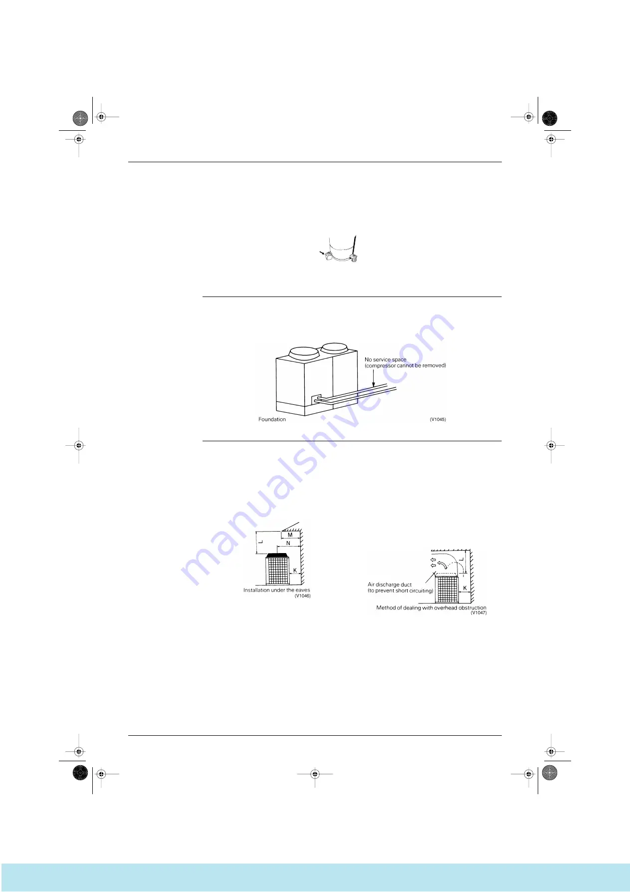
8. Remove the yellow shipping stays from the compressor support as shown in the figure (2 stays per
single compressor). Tighten the installation bolts firmly again afterwards.
Service Space
It is extremely important that enough space is left when installing the equipment to allow routine servicing
and maintenance to be carried out without undue hindrance. It is particularly important to bear in mind the
work which will be required if the compressor needs to be replaced. (The layout of the pipework can
sometimes cause considerable difficulties if the compressor needs to be changed.)
Prevention of Short
Circuits
The unit must be installed in a well ventilated area, otherwise short circuiting will occur. Special care should
be taken in situations such as that illustrated in the diagram below since additional fittings such as air
discharge ducts may also be required. (Attention should be paid to the duct’s resistance)
Fig. 3
(V0898)
Conditions for installation under the eaves
When L
≥
1m then N must be
≥
M.
When L < 1m then K must be
≥
M.
Where K is the required dimension for a single
unit installation.
Conditions for installation where there is a
horizontal obstruction above the unit
When L
≥
3m then no special action is required.
When L < 3m then a air discharge duct with
resistance within 3mmH
2
O is required.
Where K measures a little more than the
required K dimension for a single unit
installation.
Si33-102.book Page 57 Tuesday, June 26, 2001 3:18 PM
Все каталоги и инструкции здесь:
http
:
//splitoff.ru/tehn-doc.html


