SiME332106E
Field Settings for Outdoor Unit
Part 5 Field Settings and Test Operation
117
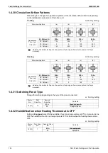
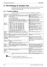
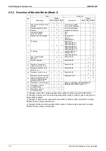
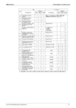
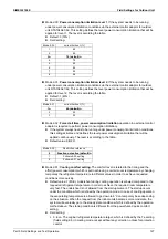
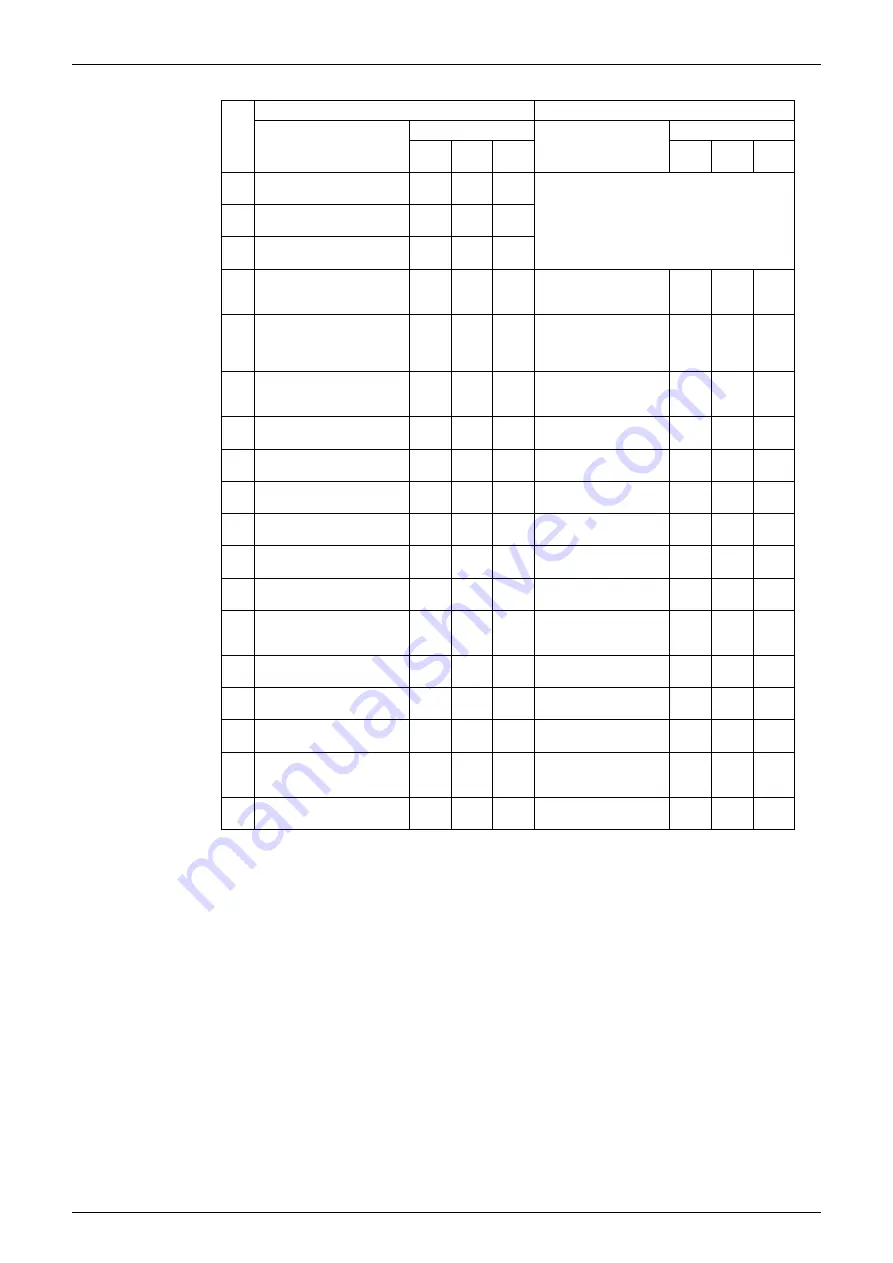
1: Numbers in the "No." column represent the number of times to press the BS button.
No.
1
Item
Contents
Description
Display
Description
Display
SEG
1
SEG
2
SEG
3
SEG
1
SEG
2
SEG
3
23
Description of retry
(latest)
1.
2
3
Refer to information in
Error Code via
Outdoor Unit PCB
on page 152.
24
Description of retry
(1 cycle before)
1.
2
4
25
Description of retry
(2 cycles before)
1.
2
5
28
Number of outdoor units
connected in a multi
system
1.
2
8
Possible 0-63
6
0
3
32
Outdoor unit PCB status
judgment
1.
3
2
0: judgment in
process
1: normal
2: abnormal
0
1
2
33
Number of abnormal
status judgment outdoor
unit PCB
1.
3
3
Possible 0-15
1
0
5
38
Number of connected RA
indoor (through BP unit)
1
3
8
Possible 0-63
6
0
3
40
Cooling comfort setting
1.
4
0
Possible 0-3
0
3
41
Heating comfort setting
(see mode 2 No. 9)
1
4
1
Possible 0-6
0
6
42
High pressure (MPa)
1.
4
2
Possible 0.1-9.99
0.
9.
1
9
0
9
43
Low pressure (MPa)
1.
4
3
Possible 0.1-9.99
0.
9.
1
9
0
9
44
Compressor total
frequency (Hz)
1.
4
4
0-999
0
9
0
9
0
9
45
Opening pulses of main
electronic expansion
valve (Y1E) (pulses/10)
1
4
5
0-999
0
9
0
9
0
9
46
Discharge pipe
temperature (°C) (Tdi1)
1.
4
6
–99-999
-
9
9
9
9
9
50
Outdoor air temperature
(°C) (Ta)
1.
5
0
–99-999
-
9
9
9
9
9
51
Compressor suction
temperature (°C) (Ts)
1.
5
1
–99-999
-
9
9
9
9
9
52
Subcooling heat
exchanger gas pipe
temperature (°C) (Tsh)
1.
5
2
–99-999
-
9
9
9
9
9
54
Compressor operation
(hours/100)
1.
5
4
0-999
0
9
0
9
0
9


