SiME332106E
Troubleshooting by Error Code
Part 6 Service Diagnosis
157
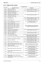
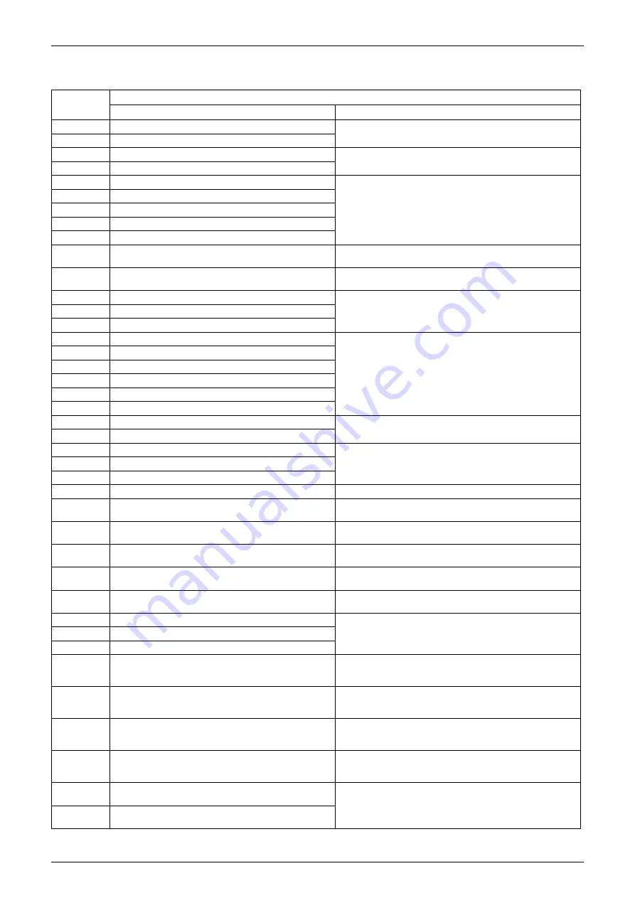
5.2.2 Outdoor Unit, System
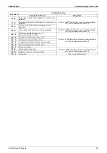
Error code
Troubleshooting
Description of error
Diagnosis
E1 - 01
Outdoor unit PCB error
Refer to the
E1
flowchart and make a diagnosis based
on the Error code shown to the left.
E1 - 02
Defective outdoor unit PCB
E2 - 01
Earth leakage detection error
Refer to the
E2
flowchart and make a diagnosis based
on the Error code shown to the left.
E2 - 06
Missing of earth leakage detection core
E3 - 01
High pressure switch activated
Refer to the
E3
flowchart and make a diagnosis based
on the Error code shown to the left.
E3 - 02
High pressure switch activated
E3 - 07
High pressure switch activated (Batch)
E3 - 13
Liquid stop valve check error
E3 - 20
High pressure switch activated
E4 - 01
Low pressure error
Refer to the
E4
flowchart and make a diagnosis based
on the Error code shown to the left.
E5 - 01
Compressor M1C lock
Refer to the
E5
flowchart and make a diagnosis based
on the Error code shown to the left.
E7 - 01
Fan motor M1F lock
Refer to the
E7
flowchart and make a diagnosis
of the fan motor based
on the Error code shown to the left.
E7 - 05
Fan motor M1F instantaneous overcurrent
E7 - 09
Fan motor M1F IPM error
E9 - 01
Electronic expansion valve coil Y1E error
Refer to the
E9
flowchart and make a diagnosis
of the relevant electronic expansion valve based
on the Error code shown to the left.
E9 - 03
Electronic expansion valve coil Y2E error
E9 - 04
Electronic expansion valve coil Y3E error
E9 - 26
Electronic expansion valve coil Y4E error
E9 - 48
Electronic expansion valve overcurrent
E9 - 54
Defective circuit
F3 - 01
Discharge pipe high temperature error
Refer to the
F3
flowchart and make a diagnosis based
on the Error code shown to the left.
F3 - 23
Overload protector activated (Q1M)
F4 - 01
Wet alarm for compressor M1C
Refer to the
F4
flowchart and make a diagnosis based
on the Error code shown to the left.
F4 - 08
Wet error for compressor M1C
F4 - 14
Indoor unit failure alarm
F6 - 02
Excess refrigerant charge error
Excess refrigerant charge was detected during test run.
F6 - 03
Excess refrigerant charge warning
Excess refrigerant charge was detected
during operation other than test run.
H3 - 02
Connection error between main PCB and inverter PCB
Refer to the
H3
flowchart and make a diagnosis based
on the Error code shown to the left.
H5 - 01
Defective overload protector for M1C (Q1M)
Refer to the
H5
flowchart and make a diagnosis based
on the Error code shown to the left.
H7 - 21
Defective fan PCB for M1F
Refer to the
H7
flowchart and make a diagnosis based
on the Error code shown to the left.
H9 - 01
Defective outdoor air thermistor (R1T)
Refer to the
H9
flowchart and make a diagnosis based
on the Error code shown to the left.
J3 - 16
Defective discharge pipe thermistor (R21T): Open
Refer to the
J3
flowchart and make a diagnosis
based on the Error code shown to the left.
J3 - 17
Defective discharge pipe thermistor (R21T): Short
J3 - 56
Discharge pipe warning
J5 - 01
Defective suction pipe thermistor (R3T)
Refer to the
J5
flowchart and make a diagnosis
of the thermistor based
on the Error code shown to the left.
J6 - 01
Defective heat exchanger deicer thermistor (R7T)
Refer to the
J6
flowchart and make a diagnosis
of the thermistor based
on the Error code shown to the left.
J7 - 06
Defective subcooling heat exchanger liquid pipe
thermistor (R5T)
Refer to the
J7
flowchart and make a diagnosis
of the thermistor based
on the Error code shown to the left.
J8 - 01
Defective heat exchanger liquid pipe thermistor (R4T)
Refer to the
J8
flowchart and make a diagnosis
of the thermistor based
on the Error code shown to the left.
J9 - 01
Defective subcooling heat exchanger gas pipe
thermistor (R6T)
Refer to the
J9
flowchart and make a diagnosis
of the thermistor based
on the Error code shown to the left.
J9 - 08
Error detection of subcooling heat exchanger gas pipe
thermistor (R6T)

