background image


1


•  

Systems  •  Installation  


9


•  Installation  


1

Field refrigerant piping


1-1

Inverter heat pump series


(1) The following materials should be used for all refrigerant piping.


Materials: Deoxidized phosphorous seamless copper pipe (for external diameters of 25.4mm or more, C1220T-0 for the rest) or equivalent


(2) Tips for insulation


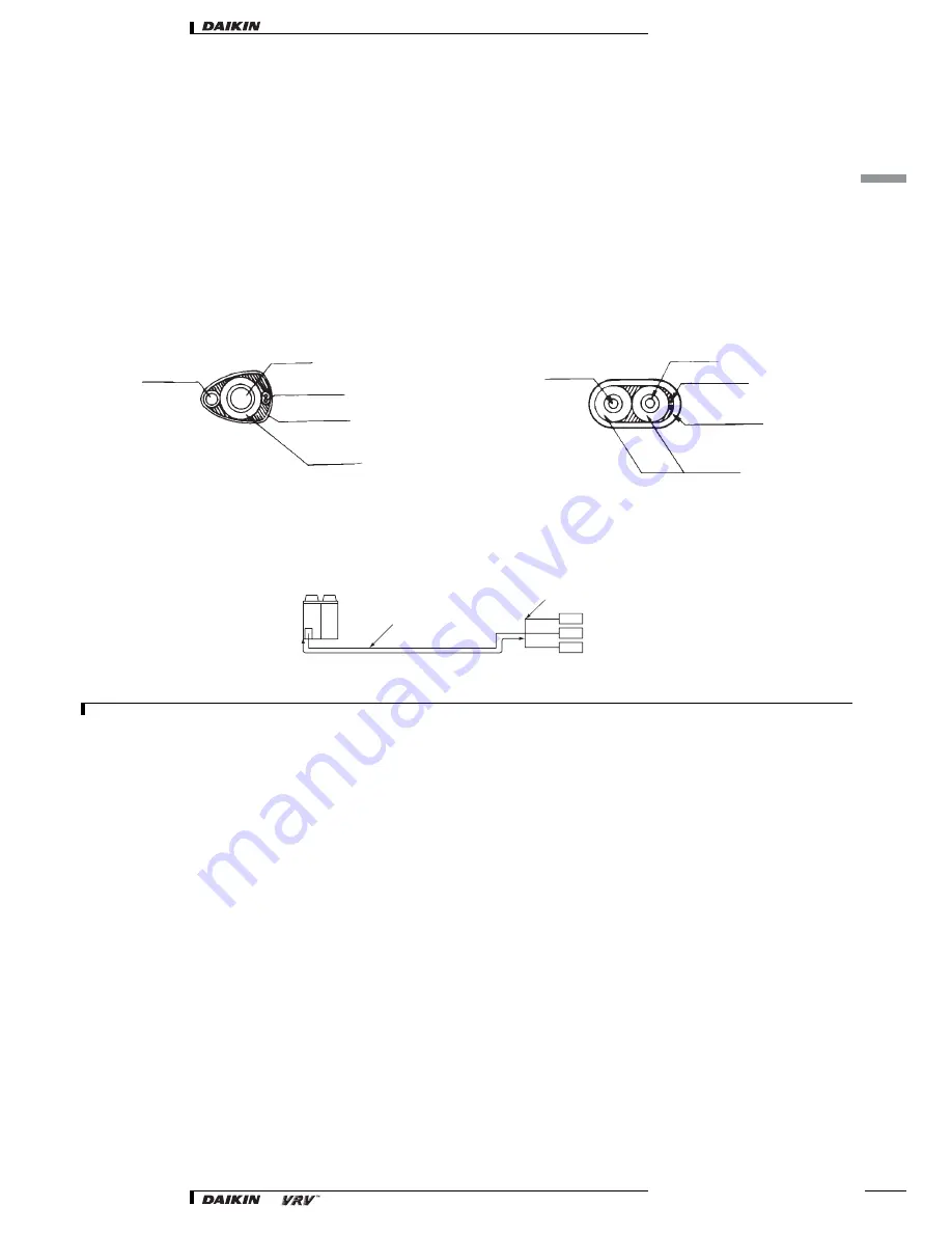
Gas piping must be insulated.

If it is considered likely that the air conditioner will be operated at temperatures between 0°C and 10°C in cooling mode then the liquid pipes must 
also be insulated.

Materials: Glass fiber or heat resistant polyethylene foam.
Thickness: 10mm or more
Heat resistance: Gas pipe : 120°C or more / Liquid pipe : 70°C or more

Insulation of single pipe only

Insulation of both liquid and gas pipe


Precautions when selecting branch piping


If the piping between the outdoor units is 90m or longer, be sure to enlarge the main pipe in the gas-side branch piping. Depending on the length 
of the refrigerant piping, the power may drop, but even in such cases it is ok to enlarge the main pipe.


NOTES


5H


P


φ


19.1


 → φ


22.2

(Lowest thickness 1.0mm)

8H


P


φ


25.4


 → φ


28.6

(Lowest thickness 1.2mm)

10H


P


φ


28.6


 → φ


31.8

(Lowest thickness 1.2mm)

Liquid pipe

Gas pipe

Electric cable

Finishing tape

Insulator

(V0523)

Liquid pipe

Gas pipe

Electric cable

Finishing tape

Insulator

(V0524)

Outdoor unit

Main pipe

Enlarge

The first refrigerant 
branching kit.

Indoor unit

(V2888)

Summary of Contents for VRV

Page 1: ...technical data Systems Installation ...

Page 2: ... installation 2 Procedure and tools for refrigerant piping work 3 Installation of outdoor units 6 1 Field refrigerant piping Inverter heat pump series 9 2 Field wiring cooling only heat pump 10 Inverter cooling only heat pump series 16 Heat recovery series 21 VRV plus 24 Installation ...

Page 3: ...pper tube shown in the below table can be applied The table is the same as the recommendation for R 22 Recommendable oil for pipe processing Daphne Master Draw 510LS 530LS 565NR 566LS Idemitsu Kosan Co Ltd Master Draw 5128 Etna Products inc Shell Drawing XA Shell Mixing amount of oil is 30mg 10m at maximum NOTE 1 When selecting and using a copper tube observe strictly the relevant standards or reg...

Page 4: ...to use torque wrench Mounting sleeves and inserts Installing indoor unit Refrigerant piping work Drain piping work Duct work 1 Make sure to conduct air tight test 2 Confirm the pressure of 3 3 MPa does not decrease for 24 hours In case of design pressure of 3 3 MPa Insulation work Electric work Connection wiring Power supply Work Setting various items Foundation work for outdoor unit 1 Vacuum grad...

Page 5: ...to use synthetic oil ether oil ester oil archi benzene oil or mixture of those oils as refrigeration oil Representative tools and devices and interchangeability Tool name Work process Usage Interchangeability with conventional tool Pipe cutter Refrigerant piping work Pipe cutting Interchangeable and can be used Flaring tool Pipe flaring Refrigeration oil Applying to flared section Use dedicated et...

Page 6: ...nditioners should not be installed in areas where corrosive gases such as acid gas or alkaline gas are produced 2 If the outdoor unit is to be installed close to the sea shore direct exposure to the sea breeze should be avoided and choose an outdoor unit with anti corrosion treatment Conduct installation work for R 407C models according to above mentioned piping work procedure Otherwise the unit m...

Page 7: ...he location in case it drips out of the unit e g in case of a blocked drain pipe 5 The piping length between the outdoor unit and the indoor unit may not exceed the allowable piping length See Example of connection 6 Select the location of the unit in such a way that neither the discharged air nor the sound generated by the unit disturb anyone 7 Make sure that the air inlet and outlet of the unit ...

Page 8: ...od The units are packed in a wooden crate and attached on a wooden pallet At delivery the package should be checked and any damage should be reported immediately to the carrier claims agent When handling the unit take into account the following 1 Fragile handle the unit with care Keep the unit upright in order to avoid compressor damage 2 Lift the unit preferably with a crane and 2 belts of at lea...

Page 9: ...he yellow shipping stays from the compressor support as shown in the figure 2 stays per single compressor Tighten the installation bolts firmly again afterwards CAUTION 1 Prepare a water drainage channel around the foundation to drain waste water from around the unit 2 If the unit is to be installed on a roof check the strength of the roof and its drainage facilities first 3 If the unit is to be i...

Page 10: ...ss 10mm or more Heat resistance Gas pipe 120 C or more Liquid pipe 70 C or more Insulation of single pipe only Insulation of both liquid and gas pipe Precautions when selecting branch piping If the piping between the outdoor units is 90m or longer be sure to enlarge the main pipe in the gas side branch piping Depending on the length of the refrigerant piping the power may drop but even in such cas...

Page 11: ...he pertinent country Do not connect the ground wire to gas pipes sewage pipes lightning rods or telephone ground wires Gas pipes can explode or catch fire if there is a gas leak Sewage pipes no grounding effect is possible if hard plastic piping is used Telephone ground wires and lightning rods dangerous when struck by lightning due to abnormal rise in electrical potential in the grounding This un...

Page 12: ...r wiring Use a round pressure terminal for connections to the power terminal block Refer to figure For wiring use the designated power wire and connect firmly then secure using the included clamping material to prevent outside pressure being exerted on the terminal board L1 L2 L3 RSXYP8 10L N Field power supply Clamp the grounding wire with power supply Grounding screw Grounding wire Wiring diagra...

Page 13: ...r Outdoor Heating cooling switching remote control cord when a heating cooling switch remote control Sold separately is connected Secure to the lock plate using the included cramping material Wiring between the units Outdoor outdoor Wiring between the units Indoor outdoor V2889 V2889 A B C A B C F1 F1 F2 F2 A B C F1 F1 F2 F2 F1 F2 F1 F2 F1 F2 F1 F2 F1 F2 F1 F2 F1 F2 F1 F2 F1 F2 C H SELECTOR TO IN ...

Page 14: ... Make the outdoor unit cable connections shown below The outdoor unit PC board A2P is factory set at Sequential start available 2 1 5 Setting the cool heat operation Heat Pump System 1 Performing cool heat setting with the remote control connected to the indoor unit Keep the cool heat selector switch DS1 1 on the outdoor unit PC board A2P at the factory setting position IN D UNIT 2 Connect the opt...

Page 15: ...position of the unit proceed as follows and refer to figure Remove the lower frontplate 1 punch a hole in the knock hole and cut the hole 2 all the way to the slit Attach the 3 sealing pads Optional parts 3 on the wiring mounting plate Optional parts 4 corresponding to the overlapped area of the front plate Install the wiring mounting plate to the front side of the side plate with the 2 delivered ...

Page 16: ...hat wiring lines do not make contact with refrigerant piping 5 Firmly close the lid and arrange the electrical wires so as to prevent the lid or other parts from coming loose Power Manual switch Switch Fuse Ground wire Ground terminal Power terminal block Unit A Unit B Unit C Power wiring between outdoor units Power wiring between outdoor units Ground branch wiring To Unit B Ground fault circuit i...

Page 17: ...r related parts do not get loose If poorly connected or loosely placed an overheat electric shock or fire may result 2 2 2 Example for the whole system NOTES 1 Up to 3 units can be connected by crossover power supply wiring between outdoor units However units of smaller capacity must be connected downstream 2 Be sure to connect the power supply wire to the power supply terminal block X1M and clamp...

Page 18: ...the transmission wiring under the following conditions Use the sheathed wire 3 wire in case of C H selector Heat pump unit only Use the sheated wire 2 wire in other case Model Supply wiring Transmission wiring Field fuse Wire Size Wire Size RSX Y 5K 20A H05VV U5G Note 1 Note 2 0 75 1 25 mm2 RSX Y 8K 35A RSX Y 10K 35A W1 Type Power supply field Electric parts box of outdoor unit See the figure 4 an...

Page 19: ...t cables are beyond these limits it may result in malfunction of transmission Max wiring length 1000m Total wiring length 2000m Max branches No of branches 16 2 Up to 16 branches are possible for unit to unit cabling No branching is allowed after branching 3 Never connect the power supply to the unit to unit cabling terminal block Otherwise the entire system may break down A B C Cool Heat selector...

Page 20: ... IN D unit When performing cool heat setting with cool heat selector Connect the Cool Heat selector remote controller optional to the A B C terminals Set the Cool Heat selector switch SS1 on the outdoor unit PC board A1P to the OUT D unit NOTES 1 For low noise operation it is necessary to get the optional External control adapter for outdoor unit For details see the Installation manual attached to...

Page 21: ... wiring and the transmission wiring apart from each other 2 No sagging of transmission wiring as shown in the figure 7 by always clamping them together 3 No contact of line with refrigerant piping 2 2 8 Gist of picking power line from the front plate Remove the front plate lower and punch a hole in the knock hole then cut it off all the way to the slit Knock hole in the front plate Apply the seali...

Page 22: ...he switch and the fuse to the power line of each equipment Connect the wires tightly and with no force upon the terminals Dress the wires so that the covers and other related parts do not get loose If poorly connected or loosely placed an overheat electric shock or fire may result Unit shall be grounded in compliance with the applicable local and national codes 2 3 2 Example for the whole system 2...

Page 23: ...0m Max branches No of branches 16 2 Up to 16 branches are possible for unit to unit cabling No branching is allowed after branching Never connect the power supply to the unit to unit cabling terminal block Otherwise the entire system may break down Power supply 3N 50Hz 380 415V See the figure 4 See the figure 6 See the figure 5 Clamp the anchor No polarity Use the conductor of sheated wire 2 wire ...

Page 24: ...g and transmission wiring apart from each other 2 No sagging of transmission wirings as shown in the figure 7 by always clamping together No contact of line with refrigerant piping 2 3 7 Gist of picking power line and transmission line Remove the front plate lower and punch a hole in the knock hole then cut it off all the way to the slit knock hole in the front plate Apply the sealing pad the line...

Page 25: ...ply rating 1 Large imbalance will shorten the life of the smoothing capacitor 2 As a protective measure the product will stop operating and an error indication will be made when power imbalance exceeds 4 of the supply rating Follow the electrical wiring diagram when carrying out any electrical wiring Only proceed with wiring work after blocking off all power Always ground wires In accordance with ...

Page 26: ...nding 1 field power supply 2 clamp the grounding wire with power supply 3 grounding screw 4 spring washer 5 flat washer 6 earth wire 7 C cup washer 8 Fix the power cord with the included clamp material to the safety catch 9 Wiring sleeve 10 Terminal board 11 Grounding wire 12 Attach the insulating sleeve 1 RXYP8 10 RXEP8 10 2 3 3 4 4 6 5 RSXYP16 18 20 RXYP16 20 RXEP8 10 Fig 18 2 3 4 5 1 3 4 6 RSXY...

Page 27: ... voltage 5 Branch wiring between outdoor units low voltage 6 insulation material 7 gas line 8 cable high voltage 9 insulation material 10 liquid line 11 cable low voltage 12 RXYP main unit Switch box 13 RXYP main unit Inverter box 14 RXEP sub unit 15 Fix to the safety catch 16 Connect the ground wire green yellow to the ground terminal 17 Extended wiring 7000 mm or less Sheathed cable or 0 75 mm2 ...

Page 28: ...s line 8 cable high voltage 9 insulation material 10 liquid line 11 cable low voltage 12 RXYP main unit Switch Box 13 RXEP sub unit Switch box 14 Connect the ground wire green yellow to the ground terminal Extended wiring 7000 mm or less Sheathed cable or 0 75 mm2 cables Always separate the high voltage wiring from the low voltage wiring in the branch wiring 15 Fix to safety catch 16 Connection bi...

Page 29: ... Example of performing cool heat with cool heat selector 1 Cool heat selector optional for heat pump unit only 2 Outdoor unit P C board A1P 3 Take care of the polarity 4 Use the conductor of sheathed wire 2 wire no polarity 5 Terminal board field supply 6 Indoor unit A B C F 1 F 2 F 1 F 2 X2M A1P 3 2 1 fig 21 A B C A B C F1 F1 F2 F2 A B C F1 F1 F2 F2 F1 F2 F1 F2 F1 F2 F1 F2 F1 F2 F1 F2 F1 F2 F1 F2...

Page 30: ... 2 Subbranching Never connect the power supply to unit to unit cabling terminal block Otherwise the entire system may break down 2 4 8 Setting the cool heat operation 1 Performing cool heat setting with the remote controller connected to the indoor unit Keep the cool heat selector switch SS1 on the outdoor unit PC board A1P at the factory setting position IN D UNIT 2 Performing cool heat setting w...

Page 31: ...2 all the way to the slit Attach the 3 sealing pads optional parts 3 on the wiring mounting plate optional parts 4 corresponding to the over lapped area of the front plate Install the wiring mounting plate to the front side of the side plate with the 2 delivered screws Pick the transmission line from the middle positioned conduit hole on the left side plate or from the front position of the main u...

Page 32: ...nt System in accordance with the ISO9001 standard ISO9001 pertains to quality assurance regarding design development manufacturing as well as to services related to the product Daikin units comply with the European regulations that guarantee the safety of the product VRV products are not within the scope of the Eurovent certification programme Specifications are subject to change without prior not...

Reviews: