Piping and Electrical Wiring Guide
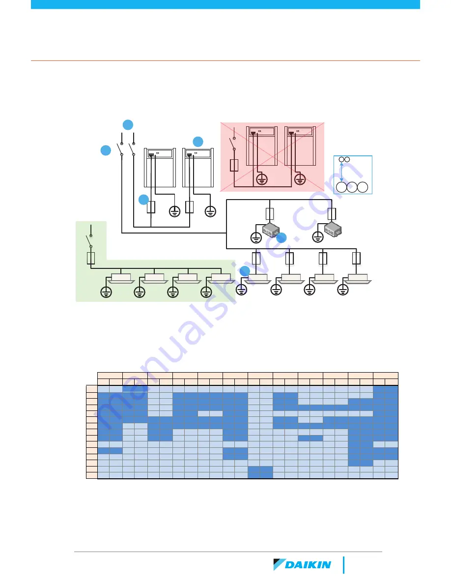
Power Wiring
1. Incoming Power from Mains
3PH4W 480 V or 208/230V
2. Disconnecting Means
3. Outdoor Unit
4. Fuse or Circuit Breaker
5. Branch Selector Box
6. Indoor Unit
Wiring ODUs in series to
a single CB is NOT an
acceptable configuration
1
2
3
5
4
6
2
"
*Allow at least 2”
spacing between
control and line
level power
conductors to
prevent signal
distortion
Wiring IDUs in series to a single
CB IS an acceptable configuration
*NEC requires all IDU Fan Coils be connected to a 15A fuse braeker by default, though multiple
can be connected to the same circuit. The chart below can be used to determine the amount
of units that can be strung together.
.
Indoor Unit Model
Si
ze
(B
tU
h)
21
FXFQ-T
FXZQ
FXUQ
FXEQ
FXDQ
FXMQ-PB
FXMQ-M
FXAQ
FXHQ
FXLQ
FXTQ-TA
FXSQ
FLA MCA FLA MCA FLA MCA FLA MCA FLA MCA FLA MCA FLA MCA FLA MCA FLA MCA FLA MCA FLA MCA FLA MCA
5
0.6
0.8
7
0.2
0.3
0.2
0.2
0.2
0.3
0.2
0.3
0.7
0.9
0.5
0.6
0.3
0.4
0.6
0.8
9
0.2
0.3
0.2
0.3
0.3
0.4
0.7
0.9
0.5
0.6
0.3
0.4
3.9
4.9
0.6
0.8
12
0.2
0.3
0.3
0.4
0.3
0.4
0.7
0.9
1.1
1.4
0.3
0.4
0.6
0.8
0.4
0.5
3.9
4.9
0.7
0.8
15
0.3
0.4
0.3
0.4
0.4
0.5
1.2
1.5
1.2
1.4
18
0.5
0.6
0.5
0.6
0.5
0.6
0.4
0.5
1
1.3
1.3
1.6
0.4
0.5
0.5
0.6
3.9
4.9
1.3
1.6
24
0.5
0.7
0.5
0.6
0.5
0.7
1.1
1.4
1.4
1.8
0.5
0.6
0.8
1
0.5
0.6
3.9
4.9
1.4
1.8
30
1
1.3
1.1
1.4
2.2
2.3
3.9
4.9
1.5
1.8
36
1.2
1.5
1.1
1.4
2.3
2.9
1.1
1.4
3.9
4.9
2
2.5
42
5.2
6.5
48
1.4
1.8
2.7
3.4
5.2
6.5
2
2.8
54
2.7
3.4
6.9
8.6
2.6
3.3
60
6.9
8.6
72
7.6
9.5
96
8.6 10.7
0.3
Summary of Contents for VRV
Page 1: ...VRV Reference Guide ...
Page 4: ......
Page 5: ...System Overview ...
Page 18: ...Piping and Electrical Wiring Guide Condensing Unit Pipe Connections 18 ...
Page 22: ......
Page 23: ...System Selection ...
Page 41: ...Design Optimization ...
Page 53: ...Controls Standards ...
Page 65: ...65 Notes ...
Page 66: ...66 Notes ...
Page 67: ......


