IOM 1281-2 • CENTRIFUGAL WATER CHILLERS 18 www.DaikinApplied.com
Installation
Field Wiring
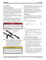
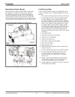
Unit Mounted Starters
The standard power wiring connection to WDC/WCC chillers
is multi-point. The power conduit entry will be at each starter
panel, whether unit mounted or remote mounted starters. For
unit mounted starters, the power connection point may be at
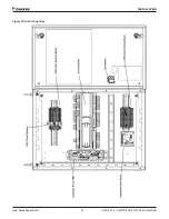
top of the panel as shown in
Figure 14
for general reference as
power entry cover plate location will vary by unit configuration.
Wiring diagrams are provided with the chiller.
Correction capacitors are not necessary since VFDs inherently
maintain high power factors and can cause harmful electrical
resonance in the system.
Only copper wiring and lugs should be used for power wiring
connections. Wiring ampacity based on 75°C conductor
rating should be used for voltages less than 2000V; 90°C or
105°C rated conductors should be used for voltages greater
than 2000V. Refer to the unit nameplate and the Daikin Tools
selection report for the correct electrical ratings.
DANGER
Qualified and licensed electricians must perform wiring.
Disconnect, lockout, and tag all electrical power sources to
the unit before servicing the compressor and/or recovering
refrigerant. An electrical shock hazard exists that can cause
severe injury or death.
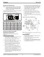
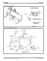
Figure 14: Unit Mounted Power Connection Point
NOTE:
Wiring, fuse, and wire size must be in accordance
with the National Electric Code (NEC). The voltage to
these units must be within ±10% of nameplate voltage
(415V units must have voltage within -13% and +6%
of nameplate voltage) and the voltage unbalance
between phases must not exceed 2%. Since a 2%
voltage unbalance will cause a current unbalance
of 6 to 10 times the voltage unbalance per the
NEMA MG-1 Standard, it is most important that the
unbalance between phases be kept at a minimum.
CAUTION
A compressor should only be brought up to speed if proper
sequence and rotation have been confirmed. Do not make final
connections to motor terminals until wiring has been checked
and approved by a Daikin Applied service technician. Serious
damage can result if the compressor starts in the wrong
direction and would not be covered by product warranty.
The compressor is covered under UL 984 by which its terminal
box is determined, per clause 8.1, by the end-use product
standard, which is UL 1995. If exceeding 1000V with controls,
Daikin Applied refers contractor to employ UL508A
The NFPA 70 (NEC) provides information pertaining to
‘minimum wire-bending space.’ Wiring to a terminal box will
vary depending on voltage, see the current version of Daikin
Applied Installation, Operation and Maintenance Manuals,
IOMM 1369 for free-standing starters.
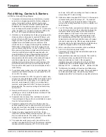
Full Metering
Remote mounted wye-delta, solid state, and across-the-line
starters require field wiring to activate the full power metering
display on the chiller’s operator interface panel. The wiring
is from the control board in the starter to the compressor
controller.
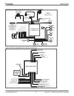
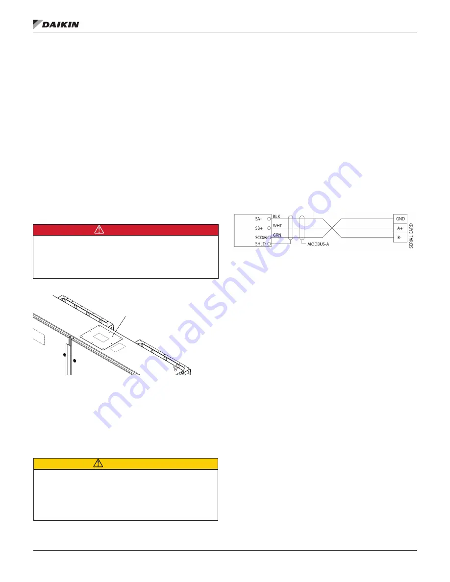
Figure 15: Wiring for Optional Display
NOTE:
• The serial card location is in the lower-center of the
compressor controller located in the chiller control panel.
• The control is located in the starter.
• The connections are (-) to (-), (+) to (+) and SCOM to
GND with a shield connection on the starter terminal
board.
• Cable is Belden 9841 or equal (120 OHM characteristic
impedance)
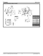
Control Power Wiring Options
The control circuit on the Daikin Applied centrifugal packaged
chiller is designed for 115-volts to the control panel. Control
power can be supplied from three different sources:
1. If the unit is supplied with a factory-mounted starter or
VFD, the control circuit power supply is factory-wired
from a transformer located in the starter or VFD.
2. A freestanding starter or VFD furnished by Daikin
Applied, or by the customer to Daikin Applied
specifications, will have a control transformer(s) in it
and requires field wiring to terminals in the compressor
terminal box.
3. Power can be supplied from a separate circuit and fused
at 25 amps inductive load. The control circuit disconnect
switch must be tagged to prevent current interruption.
Other than for service work, the switch is to remain on
at all times in order to keep oil heaters operative and
prevent refrigerant from diluting in oil.
Power Entry Cover Plate
-
Remove to cut hole in
cover plate for conduit
and then replace.


