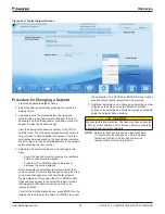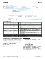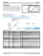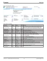
IOM 1281-2 • CENTRIFUGAL WATER CHILLERS 34 www.DaikinApplied.com
Operation
Sequencing
The Daikin Applied technician can set up different strategies
for starting and stopping networked compressors, chillers, and
pumps depending on site requirements.
The same Modes setting must be replicated on each chiller in
the system.
WCC Settings
Since the WCC is essentially two chillers combined into one
counterflow, single pass, dual-circuit chiller, the compressor on
the downstream circuit (leaving chilled water) must always be
designated as the Stage 1 compressor-first on, last off.
Operating Sequence
For multiple-chiller, parallel operation, the MicroTech controllers
are tied together by a pLAN network and stage and control
compressor loading among the chillers. Each compressor,
single or dual compressor chiller, will stage on or off depending
on the sequence number programmed into it. For example, if
all are set to “1”, the automatic lead/lag will be in effect.
When chiller #1 is fully loaded, the leaving chilled water
temperature will rise slightly. When the delta-T above setpoint
reaches the Staging delta-T, the next chiller scheduled to start
will receive a start signal and start its pumps if they are set up
to be controlled by the MicroTech controller. This procedure
is repeated until all chillers are running. The compressors will
load-balance themselves.
If any of the chillers in the group are dual compressor, they will
stage and load according to the staging instructions.
Ice Mode Operation
If available modes is set to ICE only the chiller will start (at
start delta-T) and run the Ice cycle described as follows: The
chiller will ignore softload and all demand limits and rapidly
load up to Maximum Amps setpoint. The compressor does not
unload. When the Ice LWT setpoint has been achieved, the
compressor will shutdown. The evaporator pump will continue
to run and if the evaporator LWT climbs to the Start Delta T the
chiller will restart this process.
If available modes is set to Cool/Ice with Ice mode operation
selected, the chiller will run one ICE cycle and shutdown
(compressors and pumps) no automatic restart allowed. When
the operator switches the chiller from Ice to Cool mode the
chiller will reset for operation. Changing modes can be done
through the Human Machine Interface (HMI), switches or BAS
interface, which ever is selected.
A method of migration freeze protection needs to be in place
when the chiller terminates ice mode. This is usually sensed by
the liquid line sensor and forces a condenser pump to circulate
to prevent freeze up of the condenser.
Operator Responsibilities
It is important that the operator become familiar with the
equipment and the system before attempting operation. During
the initial startup of the chiller, the Daikin Applied technician will
be available to answer any questions and instruct the proper
operating procedures. It is recommended that the operator
maintain an operating log for each individual chiller unit. In
addition, a separate maintenance log should be kept of the
periodic maintenance and servicing activities.
Operator Schools
Training courses for centrifugal maintenance and operation
are held through the year at the Daikin Learning Institute in
Verona, Virginia. The school curriculum includes instruction on
basic refrigeration, MicroTech® controllers, enhancing chiller
efficiency and reliability, MicroTech® troubleshooting, system
components, and other related subjects. For more information,
visit us at
www.DaikinApplied.com
and click on Training or
call the Training Department. Refer to the back cover of this
document for contact information.
Unit Enabling/Disabling
There are multiple options that will enable and disable the
chiller and its compressors:
1. Unit Button - Located on the upper right hand corner of
the HMI
2. Unit Enable Setting - Located in the Settings menu,
Modes tab in the HMI.
3. Manual Button - Located on the outside, front of the
control panel.
4. Remote Enable - Optional signal from a remote physical
switch or BAS signal. Replaces a jumper located on
terminal connection J31
The switches listed above work in conjunction with the “Control
Source” that is selected in the HMI via the Settings/Modes
Screen. (See
Figure 50
and
Table 13
on
page 47
.) The three
options for “Control Source” are:
1. Local - When this mode is set, a STOP button and an
AUTO button will appear at the top of the HMI screens.
This mode will ignore all functionality of a connected
Remote Switch
. It will also ignore BAS commands.
2. Switches - This is the default mode and will ignore BAS
commands.
3. Network BAS - This mode adds BAS capability to the
Digital Input functionality.
Enabling and disabling the unit and its compressors using the
switches in conjunction with the selected “Control Source” are
discussed next.

