Operation
www.DaikinApplied.com 41
IOM 1281-2 • CENTRIFUGAL WATER CHILLERS
Capacity Overrides
Compressor capacity is determined by the status of the leaving
chilled water temperature (LWT), which is a direct indicator
of whether the chiller is producing enough cooling to satisfy
the cooling load. The LWT is compared to the active chilled
water setpoint, and compressor loading or unloading ensues,
considering any capacity overrides that may be in effect.
The unit may experience a condition that will override normal
capacity control. Of the following limits, the one creating the
lowest capacity limit is in effect.
Low Evaporator Pressure
If the evaporator pressure drops below the Low Evap Pressure
– Inhibit setpoint, the unit will inhibit capacity increases. If the
evaporator pressure drops below the Low Evap Pressure -
Unload setpoint, the unit will begin capacity decreases.
High Motor Temperature
If the highest motor stator temperature is above the limit, the
unit will adjust capacity to keep the temperature within the
limits.
Demand Limit
The maximum amp draw of the compressor(s) can be limited
by a 4 to 20 mA signal on the Demand Limit analog input.
This function is only enabled if the Demand Limit Enable
setpoint is set to ON. The amp limit decreases linearly from the
Maximum Amp Limit setpoint (at 4 mA) to the Minimum Amp
Limit setpoint (at 20mA). While this override is in effect, chiller
capacity is continuously adjusted to keep the % RLA near the
requested demand limit.
Network Limit
The maximum amp draw of the compressor (s) can be limited
by a value sent through a BAS network connection and stored
in the Network Limit variable. While this override is in effect,
chiller capacity is continuously adjusted to keep the % RLA
near the requested demand limit.
Maximum Amp Limit
The maximum amp draw of the compressor(s) is always limited
by the Maximum Amps setpoint. This limit has priority over all
other functions including manual capacity control. While this
override is in effect, chiller capacity is continuously adjusted to
keep the % RLA near the limit value.
Hot Gas Bypass
All units can be equipped with an optional hot gas bypass
system that feeds discharge gas directly into the evaporator.
Light load conditions are signaled by measurement of the
percentage of RLA by the MicroTech controller. When the RLA
drops to the setpoint, the hot gas bypass solenoid valve is
energized, making hot gas bypass available for metering by
the hot gas regulating valve. This hot gas provides a stable
refrigerant flow and keeps the chiller from short cycling under
light load conditions, while also reducing surge potential on
heat recovery units.
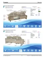
The factory default setpoint for bringing on hot gas bypass is
20% of RLA and is adjustable on Settings - Modes tab shown
on
“Figure 50: Settings View - Modes” on page 47
.
Surge and Stall
Stall and surge are characteristics of all centrifugal
compressors. These conditions occur when low load combines
with high compressor lift. In a stall, discharge gas has
insufficient velocity leaving the impeller to reach the volute
and just “sits” or stalls in the diffuser section. The compressor
sound level goes way down due to no flow and the impeller
starts to heat up. In surge, the heated discharge gas alternately
flows back through the impeller and then reverses to the volute
about every two seconds. Extreme noise and vibration occur.
The compressor is equipped with a temperature sensor that
shuts it off if these conditions occur.
Lubrication System
The lubrication system provides lubrication and heat removal
for compressor bearings and internal parts. In addition, the
system provides lubricant under pressure to hydraulically
operate the unloading piston for positioning the inlet guide
vanes for capacity control. WDC, dual compressor chillers,
have completely independent lubrication systems for each
compressor.
Only the recommended lubricant can be used for proper
operation of the hydraulic system and bearing lubrication
system. Each unit is factory-charged with the correct amount
of the recommended lubricant. Under normal operation, no
additional lubricant is needed. Lubricant must be visible in the
sump sight glass at all times.
Compressor sizes, CE079 through CE126, utilize a separate
lubricant pump located in the sump. The sump includes the
pump, motor, heater and lubricant/vapor separator system. The
lubricant is pumped through the external oil cooler and then
to the oil filter located inside the compressor housing. Oiled
centrifugal models 079-126 units utilize a water-cooled oil
cooler for the compressor. The oil coolers maintain the proper
oil temperature under normal operating conditions. The coolant
flow control valve maintains 95°F to 105°F (35°C to 41°C).
Lubrication protection for coast down in the event of a power
failure is accomplished by a spring-loaded piston in models
CE079 through 087. When the oil pump is started, the piston is
forced back against the spring by the oil pressure, compressing
the spring, and filling the piston cavity with oil. When the pump
stops, the spring pressure on the piston forces the oil back
out to the bearings. In compressor model CE 100 - 126 the
compressor coast down lubrication is supplied from a gravity-
feed oil reservoir.

