www.DaikinApplied.com 71
IOM 1322 • WATER-COOLED SCROLL COMPRESSOR
The hot gas bypass valve opening will be delayed for Hot Gas
Bypass Time set point seconds (the default is 30 seconds)
when the first compressor starts on each circuit.
EXV Control
The EXV control logic is active regardless of the expansion
valve type setting. While a circuit is in the run state, the EXV
controls suction superheat. The superheat target is 8°F. PID
logic will be used to control the superheat to the target value.
Any time the circuit is not in the run state, the EXV position
should be 0.
EXV Control Range
The table below shows the EXV range based on the number of
compressors running and number of compressors on unit.
Manual EXV Control
The EXV position can be set manually. Manual control can only
be selected when the circuit is in the run state. At any other
time, the EXV control set point is forced to auto.
When EXV control is set to auto, the manual EXV position
setting follows the auto control position.
When EXV control is set to manual, the EXV position is
equal to the manual EXV position setting.
Maximum EXV Operating Pressure
This logic only applies to TGZ units (Refrig = R134a) equipped
with electronic expansion valves. The purpose of this logic
is to prevent the operating circuit’s evaporator pressure from
exceeding the ‘MaxOpPress’ set point (found on “SET COMP
SPs (6) screen) and overloading the compressors. The
electronic expansion valves (EEV) will close to prevent the
operating circuit’s evaporator pressure from exceeding the
‘MaxOpPress’ set point.
Using the Controller
Getting Started
There are two basic procedures to learn in order to utilize the
MicroTech II controller:
• Navigating through the menu matrix to reach a desired
menu screen and knowing where a particular screen is
located.
•
Knowing what is contained in a menu screen and how
to read that information or how to change a setpoint
contained in the menu screen.
Navigating Through the Menus
The menus are arranged in a matrix of screens across a top
horizontal row. Some of these top-level screens have sub-
screens located under them. The general content of each
screen and its location in the matrix are shown in Figure 10. (A
detailed description of each menu begins on page 53.) There
are two ways to navigate through the menu matrix to reach a
desired menu screen.
One is to scroll through the matrix from one screen to another
using the four ARROW keys. The other way is to use shortcuts
to work through the matrix hierarchy. From any menu screen,
pressing the MENU key will take you to the top level of the
hierarchy. The display will show ALARM, VIEW, and SET as
shown in Figure 8. This corresponds to the second row of
screens on Figure 10. One of these groups of screens can then
be selected by pressing the key connected to it via the pathway
shown in Figure 8 on page 18.
For example, selecting
ALARM
will go the next row of menus
under
ALARM (ALARM LOG or ACTIVE ALARM)
. Selecting
VIEW will go the next level of screens under
VIEW (VIEW
UNIT STATUS or VIEW UNIT TEMP).
Selecting
SET
will go to
a series of screens for looking at and changing setpoints.
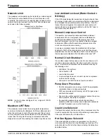
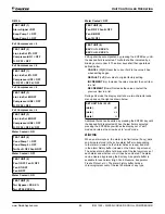
After pressing the MENU button, the top-level menu screen will
show:
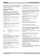
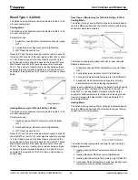
After pressing the “VIEW” menu button, a menu screen will
show:
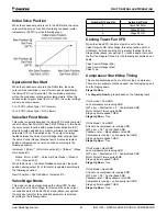
After pressing the “EVAPORATOR” menu button, the selected
data screen will show:
The arrow keys will automatically return to the “scroll” mode at
this time.
Unit Controller Operation
Summary of Contents for WGZ030DA
Page 4: ......
Page 75: ...Unit Controller Operation www DaikinApplied com 75 IOM 1322 WATER COOLED SCROLL COMPRESSOR ...
Page 76: ...IOM 1322 WATER COOLED SCROLL COMPRESSOR 76 www DaikinApplied com Unit Controller Operation ...
Page 103: ... www DaikinApplied com 103 IOM 1322 WATER COOLED SCROLL COMPRESSOR Maintenance Schedule ...
Page 104: ...IOM 1322 WATER COOLED SCROLL COMPRESSOR 104 www DaikinApplied com Troubleshooting Chart ...
Page 111: ... www DaikinApplied com 111 IOM 1322 WATER COOLED SCROLL COMPRESSOR Limited Product Warranty ...


