IOM 1322-1 • WATER-COOLED SCROLL COMPRESSOR 12 www.DaikinApplied.com
Application Considerations
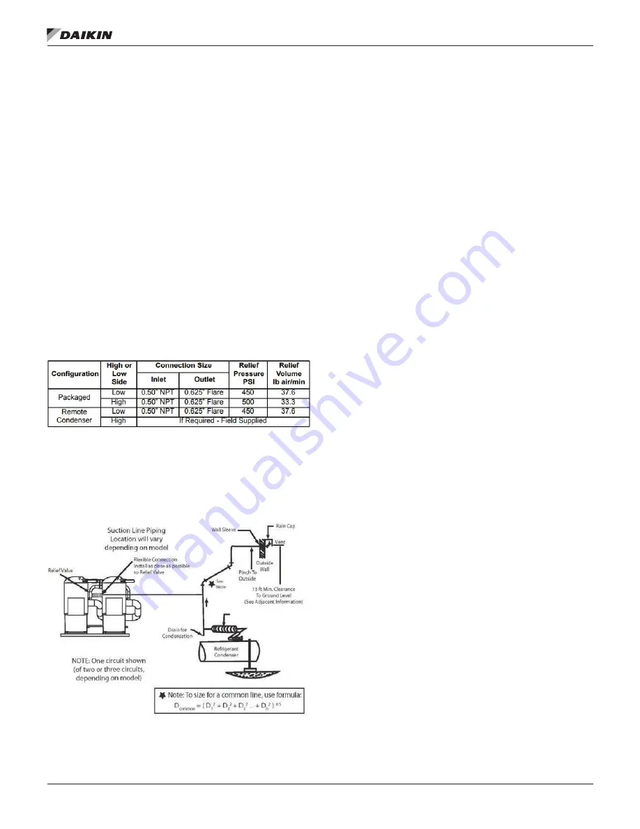
Relief Valve Piping
The ANSI/ASHRAE Standard 15, Safety Standard for
Refrigeration Systems, specifies that pressure relief valves
on vessels containing Group 1 refrigerant (R-410A) “shall
discharge to the atmosphere at a location not less than 15 feet
(4.6 meters) above the adjoining ground level and not less than
20 feet (6.1 meters) from any window, ventilation opening or
exit in any building.” The piping must be provided with a rain
cap at the outside terminating point and with a drain at the
low point on the vent piping to prevent water buildup on the
atmospheric side of the relief valve. Also, a flexible pipe section
should be installed in the line to eliminate any piping stress on
the relief valve(s).
Relief valves are located in the following places depending on
unit configuration:
• Low side with brazed plate evaporator - on the suction
line
• Low side with shell and tube evaporator - on the suction
line
•
High side on packaged unit - on the condenser shell
Table 1: Relief Valve Information
The size of the discharge pipe from the pressure relief valve
should not be less than the size of the pressure relief outlet
(5/8 in. flare). See
for pipe size when combining low
side relief on compressor suction with the condenser relief
valve.
Figure 8: Relief Valve Piping
NOTE:
Fittings should be provided to permit vent piping to be
easily disconnected for inspection or replacement of
the relief valve.
Water Pressure Drop
Water flow rates should be maintained as closely as possible
to job design values. The vessel flow rates must fall between
the minimum and maximum values shown on the appropriate
evaporator and condenser curves. Measure the water pressure
drop through the vessels at field-installed pressure taps and
check the flow rate using the following tables. Do not include
valves or strainers in these readings.
The evaporator flow rates and pressure drops shown on
the following page are for full load design purposes. The
maximum flow rate and pressure drop are based on a 6-degree
temperature drop. Avoid higher flow rates with resulting lower
temperature drops to prevent potential control problems
resulting from very small control bands and limited start up/shut
off temperature changes.
The minimum flow and pressure drop is based on a full load
evaporator temperature drop of 16-degrees.
Summary of Contents for WGZ030DW
Page 4: ......
Page 57: ...Unit Controller Operation www DaikinApplied com 57 IOM 1322 1 WATER COOLED SCROLL COMPRESSOR...
Page 71: ...Unit Maintenance www DaikinApplied com 71 IOM 1322 1 WATER COOLED SCROLL COMPRESSOR...
Page 74: ...IOM 1322 1 WATER COOLED SCROLL COMPRESSOR 74 www DaikinApplied com Troubleshooting Chart...
Page 75: ...Troubleshooting Chart www DaikinApplied com 75 IOM 1322 1 WATER COOLED SCROLL COMPRESSOR...
Page 76: ...IOM 1322 1 WATER COOLED SCROLL COMPRESSOR 76 www DaikinApplied com Troubleshooting Chart...
Page 77: ...Troubleshooting Chart www DaikinApplied com 77 IOM 1322 1 WATER COOLED SCROLL COMPRESSOR...
Page 78: ...IOM 1322 1 WATER COOLED SCROLL COMPRESSOR 78 www DaikinApplied com Troubleshooting Chart...


