IM 1044-2
Centrifugal Chillers
25
Installation Instructions for 10/11kV Motor Units
The 10/11 kV motors have additional installation requirements compare to lower voltage motors.
Installing Motor Terminal Box
For safety and shipping considerations, the chiller is shipped with a disposable protective shield over the
motor terminals and a separate field-installed terminal box.
!
CAUTION
Exert extreme care when mounting the compressor motor terminal box on the compressor to avoid damage to the
motor terminals. Terminal damage can result in costly and time consuming repair.
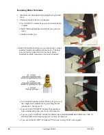
Unbolt the protective shield covering the compressor motor terminals and discard.
Install the shipped-loose terminal box as follows:
1.
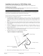
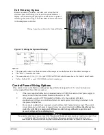
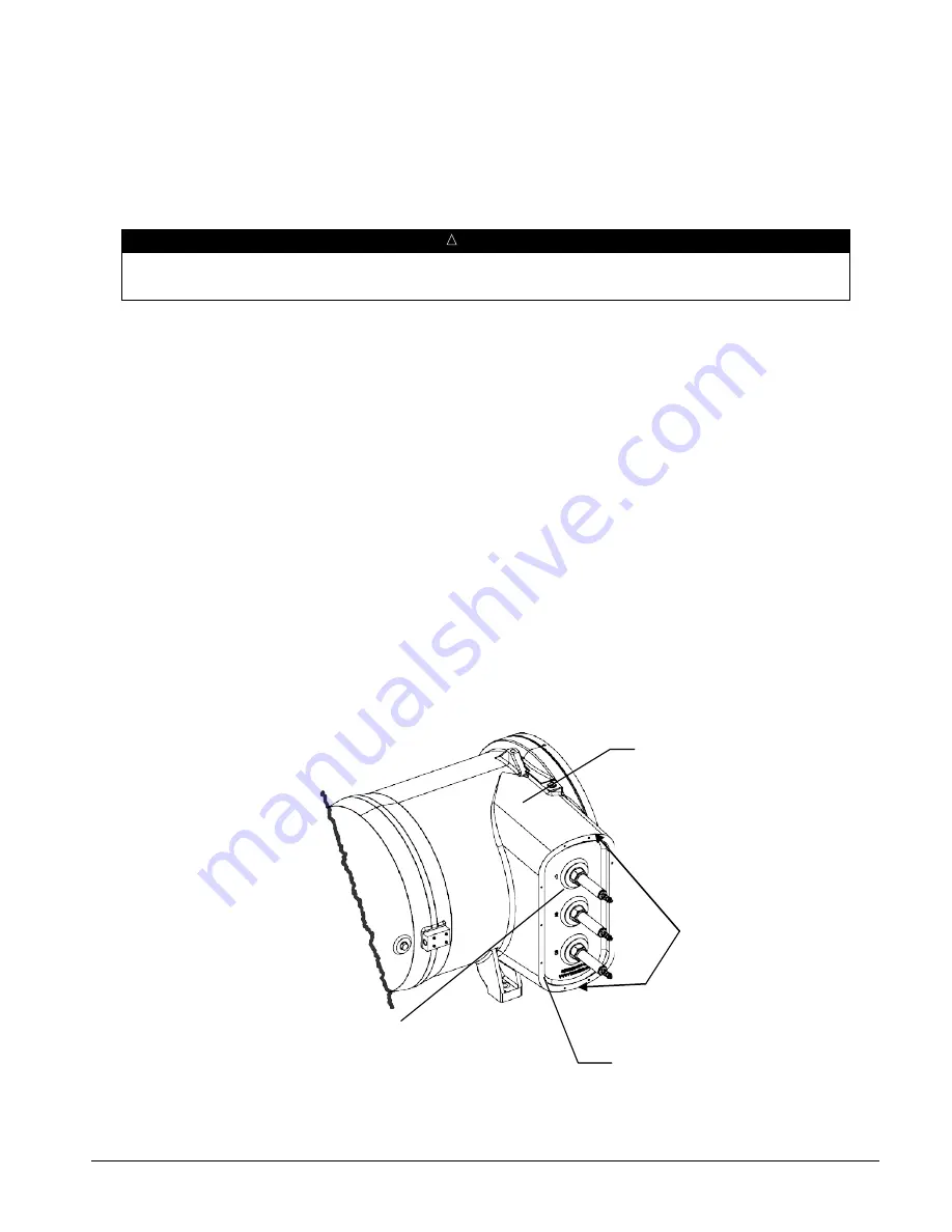
A mounting gasket is shipped with the terminal box. Mount it on the face of the compressor terminal
housing (see Figure 14) using an appropriate adhesive to hold it in place until the terminal box is
mounted. The gasket must be located such that the gasket holes align with the threaded holes in the
casting.
2.
Remove the terminal box door before lifting the terminal box helps to keep the box balanced. Lift using
lifting straps attached to the side lifting tabs. The top tab is used as a tie-off for balance, not for the main
weight of lifting.
3.
To assist in mounting the box and to provide protection to the motor terminals, screw two
¼-20 x 12 in. all-thread into top and bottom holes of the casting (see Figure 14) to provide mounting
guides for aligning the box
4.
Mount the box over the two all-threads using them as a guide and carefully position the box against the
compressor (gasket). Avoid contact with the motor terminals.
5.
Mount the box using ¼-20 x 0.75 in. bolts in all the empty holes.
Figure 14, Compressor Terminal Housing
6.
Remove the two all-thread and replace with two ¼-20 x 0.75 in. bolts.
All-thread Locations
Terminal Housing
Gasket Mounting Face
Insulate this area of the compressor
terminal housing


