42
Centrifugal Chillers
IM 1044-2
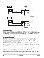
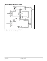
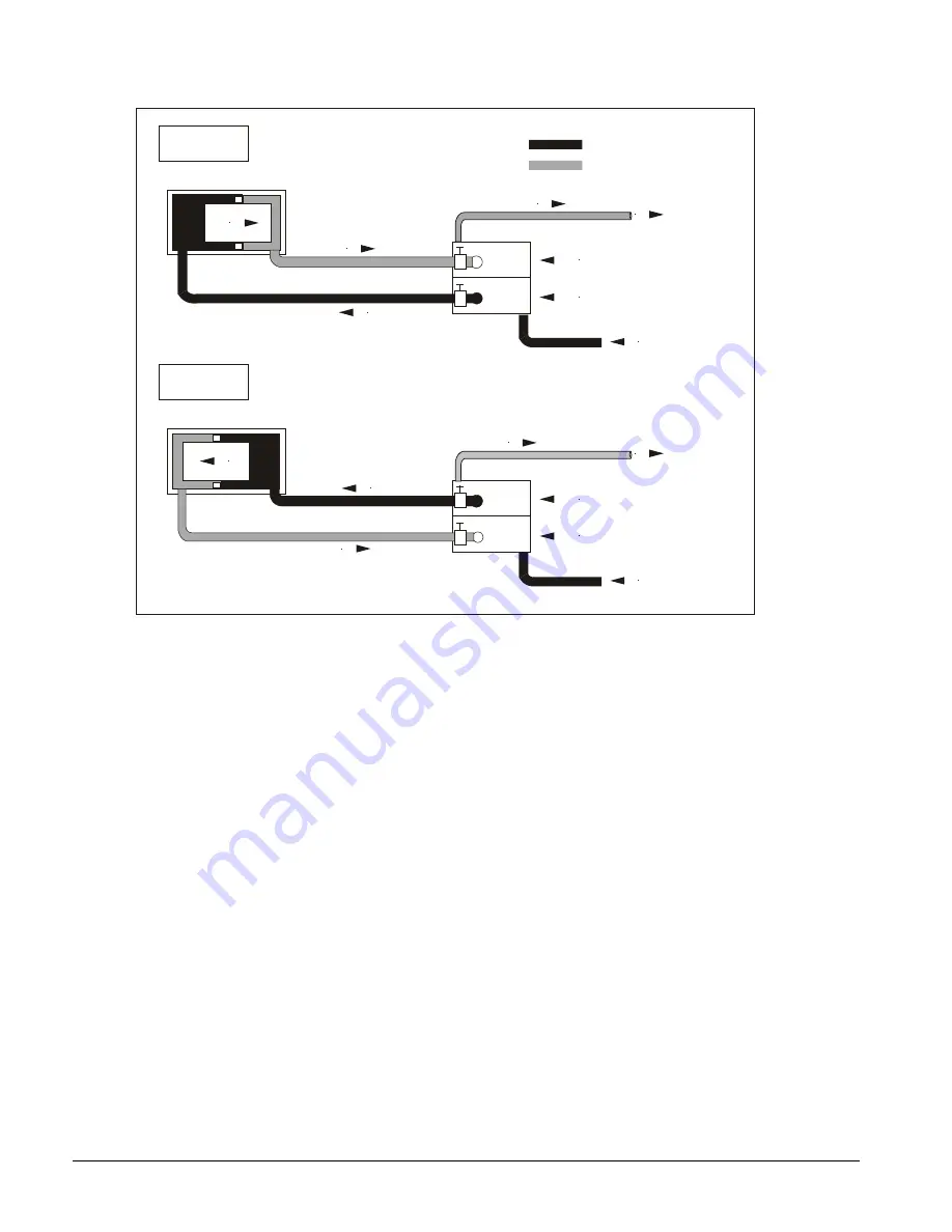
Figure 28, Vane Control Solenoid Operation, Continued
Surge and Stall
Stall and surge are a characteristic of all centrifugal compressors. These conditions occur when low load
combines with high compressor lift. In a stall, discharge gas has insufficient velocity leaving the impeller to reach
the volute and just “sits” or stalls in the diffuser section. The compressor sound level goes way down due to no
flow and the impeller starts to heat up. In surge, the heated discharge gas alternately flows back through the
impeller and then reverses to the volute about every two seconds. Extreme noise and vibration occur. The
compressor is equipped with a temperature sensor that shuts it off if these conditions occur.
Lubrication System
The lubrication system provides lubrication and heat removal for compressor bearings and internal parts. In
addition, the system provides lubricant under pressure to hydraulically operate the unloading piston for
positioning the inlet guide vanes for capacity control. WDC, dual compressor chillers, have completely
independent lubrication systems for each compressor.
Only the recommended lubricant, as shown in Table 15, can be used for proper operation of the hydraulic system
and bearing lubrication system. Each unit is factory-charged with the correct amount of the recommended
lubricant. Under normal operation, no additional lubricant is needed. Lubricant must be visible in the sump sight
glass at all times.
Compressor sizes, CE063 through CE126, utilize a separate lubricant pump located in the sump. The sump
includes the pump, motor, heater and lubricant/vapor separator system. The lubricant is pumped through the
external oil cooler and then to the oil filter located inside the compressor housing. WSC/WDC/WCC 063-126
units, single or dual compressor, all utilize a water-cooled oil cooler for each compressor.
The oil coolers maintain the proper oil temperature under normal operating conditions. The coolant flow control
valve maintains 95°F to 105°F (35°C to 41°C). Lubrication protection for coast down in the event of a power
failure is accomplished by a spring-loaded piston in models CE063 through 100. When the oil pump is started, the
Drain From Piston
#3 Outlet
SB
SA
#1 Intlet
LEGEND
Oil Under Pressure
To Oil
Pump Sump
Section “SB”
Energized
Section “SA”
De-energized
From Oil
Pump Discharge
OPENING
Oil Sump Pressure
Drain From Piston
#3 Outlet
SB
SA
#1 Intlet
To Oil
Pump Sump
Section “SB”
De-energized
Section “SA”
Energized
From Oil
Pump Discharge
CLOSING
Piston Drain

