background image

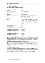
SINGLE SCREW CHILLERS IMM 

44

    Engineered for Flexibility and Performance 

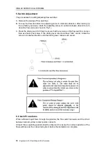
3. Flowing direction sheet 


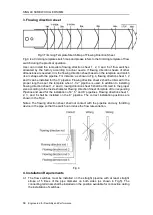
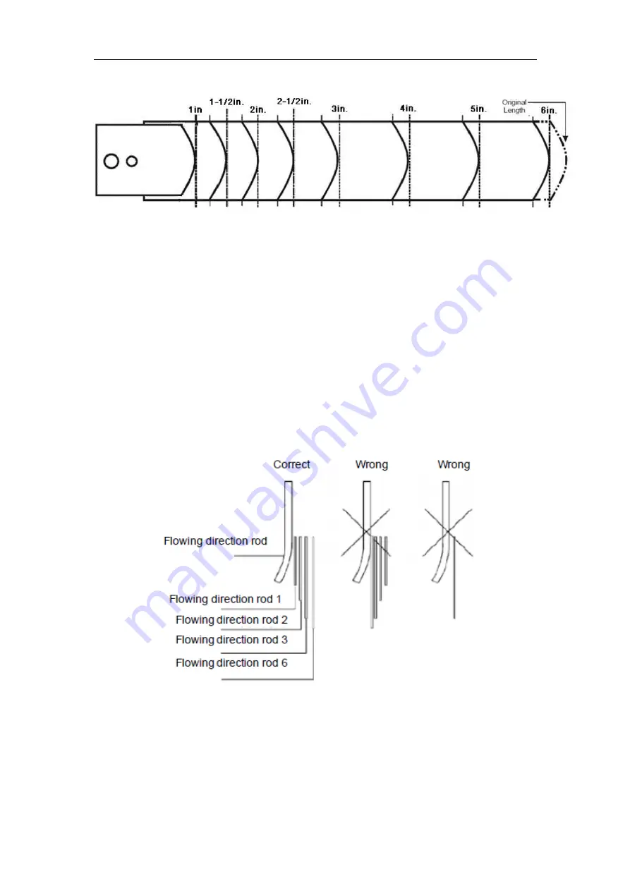
Fig.3 Trimming Template Sketch Map of Flowing Direction Sheet 

Fig.3 is a trimming template sketch map and please refers to the trimming template of flow 
switch during the practical operation. 

User  can  install  the  removable  flowing  direction  sheet  1,  2,  3  and  6  of  flow  switches 
allocated  by  the  factory  according  to  actual  needs.  If  flowing  direction  sheets  of  other 
dimensions are needed, trim the flowing direction sheet based on the template and match 
its arc shape with the pipeline. For instance: as shown in Fig.4, flowing direction sheet 1, 2 
and 3 can be installed for the 3’’ pipeline. Flowing direction sheet 2 shall be trimmed to the 
proper length as per the template when 1-1/2’’ pipeline is used. In addition to installing 
flowing direction sheet 1, 2 and 3, lowing direction sheet 6 shall be trimmed to the proper 
size according to the 

Inside Diameter Flowing Direction Sheet Template of Corresponding 

Pipeline

 and used for the installation of 4’’, 5’’ and 6’’ pipelines. Flowing direction sheet 1, 

2,  3,  and  6  shall  be  installed  on  the  8’’  pipeline.  The  correct  installation  positions  are 
shown in the Fig.4. 

Notes:  The flowing  direction  sheet  shall  not  contact  with  the  pipeline  and  any  throttling 
device in the pipe so that the switch can induce the flow rate variation. 


Fig.4 

4. Installation Requirements 

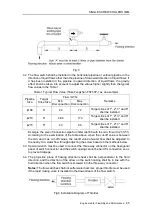
4.1  The  flow  switches  must  be  installed  on  the  straight  pipeline  with  at  least  straight 

stroke  of  5  times  of  the  pipe  diameter  on  both  sides  (as  shown  in  Fig.5).  The 
connecting terminals shall be installed on the position available for connection during 
the installation of switches.   


Summary of Contents for ZUWCM/DM

Page 1: ...ual specifies safety installation and maintenance precautions Please read through the manual before installation and use For future reference please be sure to keep it safe Engineered for Flexibility...

Page 2: ......

Page 3: ...t name plate Do not close any valve of the safety devices and please confirm all safety valves shall be installed correctly and operated normally before the operation of chiller Beware of any electric...

Page 4: ...py water after it splashes on the skin Please flush with water immediately and consult a doctor if the refrigerant liquid splashes into eyes Inspect safety devices like safety valve carefully at least...

Page 5: ...9 6 2 KNOCKDOWN OF CHILLER 21 6 3 PIPING OF THE CHILLERS 22 6 4 ELECTRIC WORKS 24 7 MATTERS TO BE CONFIRMED BEFORE TEST RUN 26 7 1 INSPECT THE POWER CIRCUIT PLEASE CONFIRM BEFORE IT BEING POWERED UP 2...

Page 6: ...QUALITY FOR CHILLER 34 APPENDIX A 36 APPENDIX B 37 APPENDIX C 43 1 DIMENSION OF FLOW SWITCHES 43 2 OPERATING CONDITIONS OF FLOW SWITCHES 43 3 FLOWING DIRECTION SHEET 44 4 INSTALLATION REQUIREMENTS 44...

Page 7: ...ZUW HCA Compressor code Refrigerant circuits Economizer Code H Vertical N None Water Cooled Single Screw Chiller Power Supply F 380V 50Hz G 400V 50Hz K 415V 50Hz Design Code Refrigerant Code C R134a...

Page 8: ...in Fig 2 2 ZUWY6Q2OFLHE3LDL2N falling film chiller as shown in Fig 2 3 and ZUWY6Q2OSF HCA Falling film chiller with Flash tank Economizer as shown in Fig 2 4 as examples to introduce each component of...

Page 9: ...SINGLE SCREW CHILLERS IMM Engineered for Flexibility and Performance 5 A View Fig 2 2 A...

Page 10: ...SINGLE SCREW CHILLERS IMM 6 Engineered for Flexibility and Performance A A View Fig 2 3...

Page 11: ...MM Engineered for Flexibility and Performance 7 compressor starter cabinet Evaporator condenser Flash tank Economizer A View condenser inlet condenser outlet evaporator inlet evaporator outlet control...

Page 12: ...parator in high temp pressure 2 Oil is separated from refrigerant in oil separator The former goes back to compressor and the later goes to condenser 3 Refrigerant gas is condensed to high pressure li...

Page 13: ...tor The former goes back to compressor and the later goes to condenser 3 Refrigerant gas is condensed to high pressure liquid and then goes through expansion valve to the Flash tank Economizer Gas and...

Page 14: ...ant in air C Strictly follow this manual during installation Inappropriate installation might cause refrigerant leakage electrical shock fire accident etc D Electrical cable shall be wired or connecte...

Page 15: ...explosion will happen when flammable gas concentration achieves certain level B Chiller shell shall be grounded Ground cable shall avoid gas pipe water pipe lightning rod or telecom cable wrong ground...

Page 16: ...cleaning agent refrigerant etc Illegally discharged waste liquid or gas will harm health and environment K It is forbidden to close the AC contactor to start the compressor It may cause electric shock...

Page 17: ...sed for preserving animals plants precision devices artworks etc otherwise it will degrade their quality B Do not operate the chiller with wet hands This is one of the causes of electrical shock C It...

Page 18: ...the compressor and discharge pipes It will cause scald S Drain the water in chiller unit if chiller will stop for a long time Before long period stop drain the water or add anti freeze in chiller or...

Page 19: ...the evaporator and oil separator No relief valve on the condenser because it connects the oil separator in order to release the pressure of vessel when it is too high The relief valve installation fo...

Page 20: ...djust the cut off valve to isolate it and the other relief valve can protect the system at the same time the damaged valve could be changed To set the pressure of relief valve please refer to the Engi...

Page 21: ...onnection 5 2 Chiller Lifting The lifting mode is shown in Fig 5 1 Parameters on nameplate shall be taken as the criteria for dimensions and weight Fig 5 1 5 3 Lifting Requirements of Chiller A It is...

Page 22: ...r or starter lift lug to lift the entire chiller B The lifting cable shall not contact chiller pipes It might crack the pipes 5 4 Horizontal transiting To prevent bending of chiller main foundation pl...

Page 23: ...tal electrical parts etc Locate the cooling tower in appropriate place to avoid cooling water contamination It is forbidden to locate the chiller near coast plating plant chemical plant etc where the...

Page 24: ...g isolator mounting in which AB is the edge length of the spring isolator and L is the distance between the two bolt holes on the bottom Anchor the spring isolator with bolts at two holes on the botto...

Page 25: ...and then inspect all of the welding connections and connection positions for leakage for the second time If any leakage detected discharge the refrigerating engine oil if provided in the chiller and...

Page 26: ...the pipeline support 3 Ensure that the unit in and out water pipe will not bear the excessive force on equipment B For proper Flow Rate 1 Check the air tightness of pipe works before connecting chille...

Page 27: ...rain port periodically Consider its service space during installation 4 In order to easily clean chiller tubes isolation valves are requested for both inlet and outlet chiller pipes To easily remove t...

Page 28: ...listed below is recommended specific to the low cooling inlet water temperature condition Fig 6 4 As shown in the figure the two way motorized valve is installed in the leaving pipe of cooling water a...

Page 29: ...he ash on the electrical components in control cabinet before starting the electric work Don t break the terminals during cable connecting Clean the cabinet and tools when above work is finished D Att...

Page 30: ...rect grounding as per outside wiring requirements D Control cabinet interior must be cleaned Clear the dust produced during installation and electrical works before the cabinet being powered up 7 2 Ac...

Page 31: ...er side stated in the chiller contract C Leakage check Ensure no leakage at flange bushing and connector D Ensure no air mixed When water has noise water pressure changes during equipment installation...

Page 32: ...l discharging valve On Bottom of oil separator Pollution discharging valve Off Suction Pipeline Suction valve if available On Oil Return Pipeline Drainage tube ball valve if available On Liquid Supply...

Page 33: ...e above is cooling outlet water temperature The figure above just indicates the chiller capacity control ability along with fluctuation of the cooling outlet water temperature and the capacity control...

Page 34: ...d the air conditioning cooling equipment may also be affected in negative way Additionally while there is a bypass circuit on the equipment please ensure that the water flow in each water circuit is g...

Page 35: ...glycol solution concentration reduces below the setting point b Check that if the air is mixed into the water pipes The air may get into the water pipes even though you have vented it at first Please...

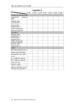
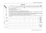
Page 36: ...ibility and Performance 9 6 Routine Maintenance In order to keep chiller running regularly maintenance with adjustment and record is required Maintenance table is shown in appendix A See Appendix B fo...

Page 37: ...lean heat exchanger when then chiller stops for a long time or the vessels will be rusted and tubes will be damaged by ice when ambient temperature drops below zero After the water is drained please c...

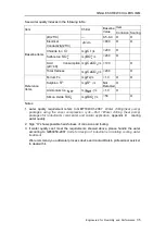
Page 38: ...ations of Hydrogen sulfide 5 mg m3 Concentrations of Nitrogen oxide 5 mg m3 Concentrations of Chloride 1 mg m3 Concentrations of Hydrogen chloride 5 mg m3 Installation indoor installation without dire...

Page 39: ...ted O Ammonium Ion NH mg NH L 1 0 O Silicon Oxide 2 SiO mg 2 SiO L 50 O Notes 1 water quality requirement refers to GB T18430 1 2007 Water chilling heat pump packages using the vapor compression cycle...

Page 40: ...water temperature Enter Leaving water pressure drop kPa Evaporator Entering water temperature Leaving water temperature Enter Leaving water pressure drop kPa Entering water temperature Others Dischar...

Page 41: ...ischarge superheat of R410A chiller shall be larger than 7 C Monthly Inspection 1 Color of compressor oil new oil is clean and the dark brown or cloudy oil shall be replaced the compressor shall be ov...

Page 42: ...rmal operation is detected Electric expansion valve capacity control Abnormal insulation resistance is detected Oil filter The pressure difference exceeds 1 5 bar during operation Discharge valve Ther...

Page 43: ...ical or Chemical Heat transfer temperature difference more than 3 C Water pressure drop see chiller specs To check whether the rubber gaskets are damaged if the pressure drop value is lower than 60 Ra...

Page 44: ...luid flows during closing the chiller control controller The input or output of signal is abnormal Fuse Disconnection Contactor Contact electric corrosion or noise are detected during the running Sens...

Page 45: ...f value exceeds the calibration value 0 05 0 08 Low voltage switches The cut off value exceeds the calibration value 0 05 0 03 Wiring for loose contacts Retighten if any Others Check Power supply Powe...

Page 46: ...ace cycle 2 The components shall be replaced as per the interval and operating time whichever is earlier 3 Customer shall check and record the items on daily and monthly basis and other inspection ite...

Page 47: ...ormative Appendix Instructions for Flow Switches 1 Dimension of Flow Switches Fig 1 Dimension 2 Operating Conditions of Flow Switches Fig 2 Switches Motion When sufficient liquid passes through the pi...

Page 48: ...oper length as per the template when 1 1 2 pipeline is used In addition to installing flowing direction sheet 1 2 and 3 lowing direction sheet 6 shall be trimmed to the proper size according to the In...

Page 49: ...be installed Example the size of connection pipe for chiller is 168 with the min flow of 32 5 m h According to the examination of the table above when the cut off value is between the min and max cut...

Page 50: ...wn in Fig 1 C Press the driving lever for times to ensure that the set value of the flow switch is no less than ex nfactory set value If the driving lever returns without click sound rotate the screw...

Page 51: ...wiring diagram The control switch fails to actuate Check the wiring and check whether the flowing direction sheet has contacted with the pipeline The switch actuates when liquid flows and does not re...

Page 52: ...er the Remote Start Stop function connect a switch user supply between No 21 and No 35 terminals can realize the function 5 If users order the Leaving Water Temp Reset function connect a switch user s...

Page 53: ...Users need to connect the grounding bus bar of the cabinet to the ground 9 If users order the Ice Heat function connect the switch user supply to the corresponding terminals to switch the modes 10 Acc...

Page 54: ...e service according to different client s needs Contact Company Address No 33 Checheng Avenue Economic and Technological Development Zone Wuhan City Hubei Province 430056 China Printing may be differe...

Reviews: