pressure at which the knob automatically comes
out. This pressure should be 20 to 45 psi (138 to
310 kPa).
18. Close the drain cocks, recharge the system, and
completely drain the primary reservoir. On ve-
hicles equipped with a DRM or AD-IS with the air
dryer attached to the reservoir, the secondary
reservoir pressure should not drop below 65 psi
(448 kPa). On vehicles equipped with single
check valves, where the air dryer is not attached
to the reservoir, the secondary reservoir should
not lose air pressure.
19. On tractors only:
19.1
Start the engine and build the system air
pressure to governor cut-out.
19.2
Shut down the engine and leave the park-
ing brakes released.
19.3
Completely drain the primary reservoir.
19.4
Make a modulated service brake applica-
tion by depressing the brake pedal. The
front brakes should apply and release
and the brake lights should illuminate. In
addition to the front brakes, with the
trailer supply knob pushed in, the trailer
control coupling should deliver air during
the brake application.
20. On trucks only:
20.1
Start the engine and charge the air sys-
tem until governor cut-out.
20.2
Shut down the engine and leave the park-
ing brakes released.
20.3
Completely drain the primary reservoir.
20.4
Make a modulated service brake applica-
tion. Both front and rear brakes should
modulate. At a steady full brake applica-
tion, the pressure should not drop more
than 10 psi (69 kPa) within five minutes.
21. Drain all reservoirs and remove the gauges from
the service reservoirs. Close the reservoir drain
cocks.
22. Remove the chocks from the tires.
42–12 Bendix E-6 Foot Control
Valve Inspection and
Lubrication
1.
Remove the brake valve from the vehicle; see
Group 42
, of the vehicle Workshop Manual.
2.
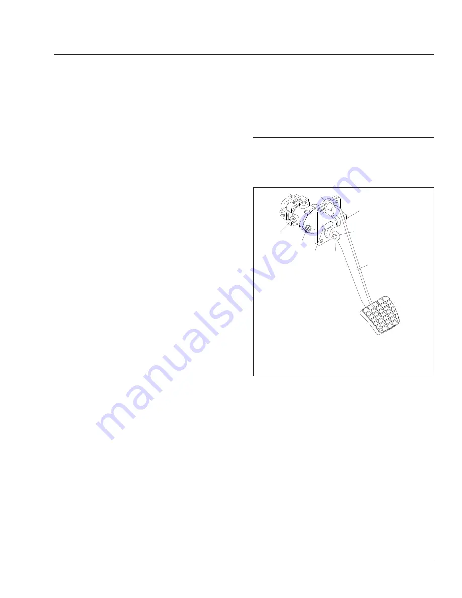
Remove the roll pin from the brake pedal pivot
pin. See
3.
Remove the brake pedal pivot pin.
4.
Remove the brake pedal.
5.
Check the brake pedal mounting plate adapter
for signs of wear or cracks at the bosses (the
area from which the pivot pin was removed). Re-
place it if necessary.
6.
Check the brake pedal rollers for signs of wear
or cracks. Replace the rollers as needed.
7.
If the rollers are replaced, replace the roller pin,
install a new cotter pin, bend it to 90 degrees
and apply Torque Seal (OPG F900 White) to the
cotter pin.
8.
Remove the plunger from the valve. Using alco-
hol, clean the existing grease from the plunger.
09/10/2004
f430405
1
2
3
4
6
7
8
5
1.
E-6 Foot Control Valve
2.
Mounting Plate
3.
Nut and Washer
4.
Pivot Pin
5.
Roll Pin
6.
Roller
7.
Roller Pin
8.
Pedal
Fig. 9, Brake Pedal and Valve Assembly
Brakes
42
Business Class M2 Maintenance Manual, November 2015
42/11
Property of American Airlines


