background image

For operators (including
the machine administrator)

No. 100027907V00

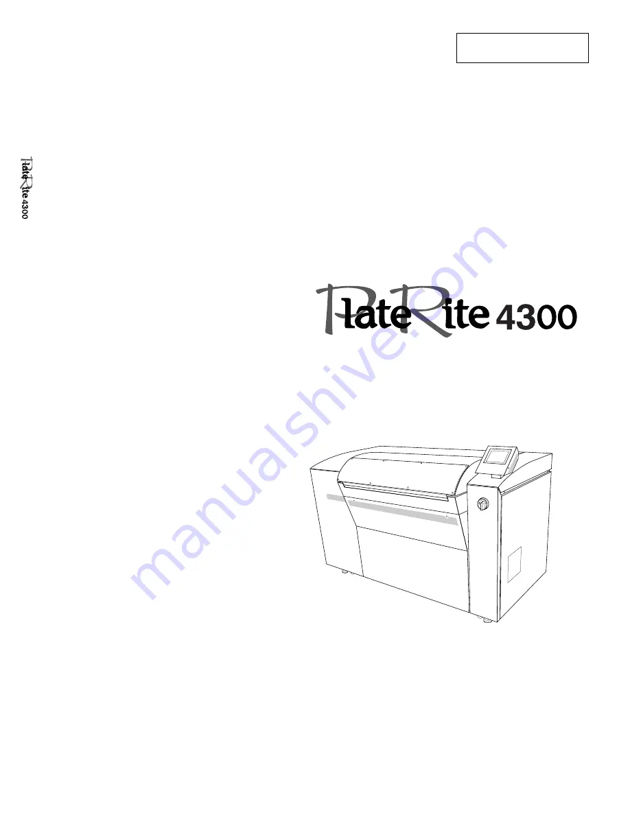
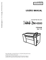
  PT-R4300

Ver. 1.0-

Thermal Plate Recorder

USERS MANUAL

Before attempting to operate this product, you should thoroughly read and fully

understand the contents of this manual.

The administrators of the PT-R4300 should not let anyone who does not

understand the contents of this manual operate or inspect the PT-R4300.

Thermal Plate Recorder                       Ver. 1.0-

USERS MANU

AL

• Printed on recycled paper.

Summary of Contents for PLATE RITE 4300

Page 1: ...MANUAL Before attempting to operate this product you should thoroughly read and fully understand the contents of this manual The administrators of the PT R4300 should not let anyone who does not unde...

Page 2: ...the manual is lost write down or make a copy of the Dainippon Screen sales offices and agencies listed at the end of this manual WARNING Do not turn on the power of the PT R4300 until you fully unders...

Page 3: ...instrument is used improperly This signal word indicates a potentially hazardous situation which if not avoided or properly handled could possibly result in minor or moderate injury CAUTION Signal wo...

Page 4: ...y or liability for equipment transferred without regard to proper export import regulations or procedures Harmonics experiments Since the EUT is fall into definition as high power equipment same or ov...

Page 5: ...eous please contact Dainippon Screen Expressions used in this manual In this manual procedures and explanations have alert symbols and signal words to signify degree of importance similar to safety wa...

Page 6: ...lains the basic procedures for operating the PT R Chapter 5 User Menu This chapter explains the procedures for setting PT R parameters Chapter 6 Maintenance This chapter explains daily maintenance and...

Page 7: ...lation 2 3 4 Load Tolerance of Building 2 4 5 Ground Connections 2 4 6 Power Supply and Power Cables 2 4 3 Names of Each Part 1 The PT R4300 3 2 2 Accessories 3 6 2 1 Standard Accessories 3 6 2 2 Opti...

Page 8: ...Setting the Printing Machine Information 5 21 4 1 Selecting the Plate 5 21 4 2 Entering Comments 5 22 4 3 Setting the Grip Direction 5 23 4 4 Setting the Leading and Trailing Grip Margins 5 23 4 5 Set...

Page 9: ...r 6 11 4 Cleaning the External Cover Filter 6 12 PT R4300 Maintenance and Inspection Chart 6 13 5 Maintenance Parts 6 14 5 1 Consumables 6 14 5 2 Information to be Specified when Ordering Parts 6 14 7...

Page 10: ...x...

Page 11: ...Chapter 1 Ensuring Safety 1 This chapter gives information necessary for safe use of the PT R...

Page 12: ...interlocks disengaged may result in serious personal injury The PT R has been classified as a Class I Laser Product complying with 21 CFR Chapter 1 Subchapter J and Class 1 Laser Product based on JIS...

Page 13: ...s receptacle on the back of the PT R Doing so could lead to damage to the tray or an accident resulting from tripping CAUTION Do not cover the PT R with a cloth or block its air vents in any way NOTE...

Page 14: ...nnecting the power cables of the PT R to the switchboard CAUTION To prevent current overload install a current breaker at the power supply before connecting the PT R to the power supply Power cables a...

Page 15: ...in case of an emergency Forced drum stop switch Fig 1 2 Forced drum stop switch WARNING In order to prevent accidents be sure to turn off both the PT R and building side power switches after work or b...

Page 16: ...offers courses on the proper handling of our products whenever needed Please attend a course before attempting to operate the PT R Application for these courses can be made at any Dainippon Screen of...

Page 17: ...objects in front of or cover a warning or caution label If a warning or caution label has peeled off or is dirty replace it with a new label Failure to replace the label is extremely dangerous NOTE If...

Page 18: ...ISIBLE Label indicating the class power and wave length of the laser DANGER INVISIBLE LASER RADIATION WHEN OPEN AND INTERLOCKS DEFEATED AVOID EYE OR SKIN EXPOSURE TO DIRECT OR SCATTERED RADIATION VORS...

Page 19: ...cause undesired operation This Class A digital appartus meets all requirements of the Canadian interference Causing Equipment Regulations Cet appareil numerique de la Clase A respecte toutes les exige...

Page 20: ...AS APPLICABLE TO STANDARDS 21 CFR CHAPTER I SUBCHAPTER J MADE IN JAPAN T MADE IN JAPAN Z830B L8 M O D E L MFG No D A T E V O L T S A M P S P H A S E Hz kW A V Label indicating that this is a Class 1 L...

Page 21: ...nterlocks Operating the PT R with the interlocks disengaged may result in serious personal injury If any of the doors are opened during exposure the interlocks will activate and automatically stop the...

Page 22: ...NUAL 1 12 Soft switch for drum slowdown Interlock switch for rear cover Interlock switch for right side cover Fig 1 10 Interlock switches right side Interlock switch for left side cover Fig 1 9 Interl...

Page 23: ...battery has a life of five to ten years When it expires it should be disposed of carefully using special procedures for handling harmful substances When disposing of the PT R please contact the place...

Page 24: ...y provide The following are requirements regarding product use and disposal for environmental preservation Please read thoroughly and faithfully observe the contents in the same manner as you would fo...

Page 25: ...handling of dangerous and toxic waste Label the item for disposal to indicate what it is and to indicate that it is a dangerous and or toxic waste Making sure it will be distinguished from other wast...

Page 26: ...PT R4300 USERS MANUAL 1 16 End of Chapter 1...

Page 27: ...Chapter 2 This chapter explains precautions for installing and moving the PT R Installing and Moving the PT R 2...

Page 28: ...e end of this manual 2 Installation Location Do not install the PT R in any of the following locations as safety problems failures and malfunctioning may result Locations directly exposed to sunlight...

Page 29: ...nance leave at least 800 mm open around the periphery of the PT R Keep the floor free of obstacles and keep a path to the building side power switch clear CAUTION Keep 200 mm open around the periphery...

Page 30: ...ualified electrician select the above items and perform the connections 6 Power Supply and Power Cables Have electrical work performed by a qualified electrician Make arrangements to obtain the power...

Page 31: ...Chapter 3 Names of Each Part 3 This chapter gives an overview of the PT R and explains its configuration...

Page 32: ...ction Fig 3 2 Full view front and left sides Operation door Ejection table Positioning labels for large sized plate Insertion table Transport roller Positioning labels for small sized plate External c...

Page 33: ...filter Punch debris outlet Peripheral device connectors Rear cover Attachment hooks for punch debris receptacle Power cable connector Vacuum hose connector Exposed plate from the rear outlet External...

Page 34: ...AL 3 4 Fig 3 5 Peripheral device connectors F PIF connector 25 pin F PIF connector 50 pin Service connector RS 232C 9 pin Developer unit connector 25 pin Blower control connector 14 pin Power supply c...

Page 35: ...s of Each Part Fig 3 6 Inside of front cover Fig 3 7 Inside of rear cover Drum Optics unit Front cover attachment hooks Rear cover attachment hook Drum Cleaning roller Rear cover attachment hook Punch...

Page 36: ...d with the PT R 2 1 Standard Accessories Blower unit Blower unit Vacuum hose 2 m Communication cable UL2464 AWG24 7P 2 m Power cable 0 75 mm2 3 wires 300V for blower unit which plugs into PT R 2 m Pun...

Page 37: ...The following items are available as options For more information or to place an order contact one of the Dainippon Screen offices or agents listed at the end of this manual Punch unit types Dainippon...

Page 38: ...PT R4300 USERS MANUAL 3 8 End of Chapter 3...

Page 39: ...This chapter explains the basic procedures for operating the PT R Chapter 4 Basic Operation 4...

Page 40: ...refer to 3 1 Turning On the Power A memory check of the PT R begins When the memory check ends the initial screen appears on the display Fig 4 1 Initial screen 2 Press START Initialization of the PT...

Page 41: ...the PT R and the buzzer beeps repeatedly Fig 4 4 Plate set request screen 7 Press OK The buzzer stops and the following screen appears Fig 4 5 Operation door open screen 8 Press OPEN The lock is rele...

Page 42: ...here they are connected The cables to be connected are the two PIF cables The power cable and communication cable for blower control were connected during installation The PIF cable connects the PT R...

Page 43: ...power switches of the peripheral devices by throwing the switches to the side 4 Rotate the power switch lever of the PT R in the clockwise direction until it is vertical Power is being supplied when y...

Page 44: ...wer switch window 3 Verify that the PT R power has been turned off and then turn off the peripheral devices by throwing the switches to the side 4 Turn off the building side power switch CAUTION After...

Page 45: ...personal computer Please contact a Dainippon Screen sales office or agent Fig 4 8 Check sum error screen When the memory check ends the initial screen appears Fig 4 9 Initial screen 2 Press START to b...

Page 46: ...ypes can be registered In addition to the 15 types No 1 through 15 that can be registered there are also 15 types No 31 through 45 that have been pre registered and these can be copied to No 1 through...

Page 47: ...image size type A Type A Set the number of the printing machine information registered in the PT R as the information for a virtual printing or multi entry machine By selecting a virtual printing mach...

Page 48: ...ges which are smaller than the plate size Minimum image size Plate Maximum image size CAUTION When using type B the output image will exceed the effective exposure area In this case the image data out...

Page 49: ...of the plate excluding approximately 15 mm at the leading edge and 12 mm at the trailing edge as shown below CAUTION If the leading and trailing grip margins are set to less than 15 mm or if the imag...

Page 50: ...d to the PT R Load plate using an exposure instruction from the host computer Load plate before an exposure instruction comes from the host computer Set next plate while exposure is in progress CAUTIO...

Page 51: ...Be careful of the following when handling plates When storing plates the environment should be the same as that for the PT R and the plates should be stored in a horizontal or inclined type plate rack...

Page 52: ...hem on the roller and turn the knob until the plate hits the shutter at the back Positioning labels Roller Shutter Knob Large sized plate Fig 4 20 Positioning large sized plate 6 Close the operation d...

Page 53: ...ding to the size of the plate on the left and right positioning labels and push the plate in until it touches the shutter inside the transport 4 Close the operation door by hand until it locks The pla...

Page 54: ...his is done the next plate waits on standby until exposure is completed When exposure is completed and the exposed plate is ejected to the ejection table the plate that was on standby is loaded and wa...

Page 55: ...and then remove the exposed plate 7 If another plate is to be set repeat this procedure from step 2 If no more plates are to be set close the operation door NOTE When using Version 4 3 Rev F or Versio...

Page 56: ...be in the ready state or the following message will appear during PT R initialization Ex600 or Ex601 Either the conveyor processor or stocker is not turned on or is in the busy status or is in error s...

Page 57: ...essor solution replenishment and waste solution tank errors do not occur Stopping the buzzer when ejecting plates You can set the machine so that the buzzer will not sound when plates are ejected For...

Page 58: ...printing process This causes ink to spread by several percent In older CTP plate and image processing systems the effect is sometimes partially corrected due to the influence of soft dots the area of...

Page 59: ...en the plate is made Similarly linear plates print several percentage points thicker than positive plates To match plates created with conventional positive or negative film to the PT R reduce the dev...

Page 60: ...PT R4300 USERS MANUAL 4 22 End of Chapter 4...

Page 61: ...This chapter explains the procedures for setting PT R parameters Chapter 5 User Menu 5...

Page 62: ...creen to display the offline screen To return to the online screen press ONLINE The hierarchy of the offline mode is as shown below Press ESC at any screen to return the previous screen NOTE Set infor...

Page 63: ...tions Select User maintenance and press OK Set plate load unload test exposure and other user settings For more details refer to 6 Manually Loading the Plates to 9 Test Exposure Select Information and...

Page 64: ...sing OK OK ESC 20 CLR 7 8 9 4 5 6 1 2 3 0 ENT Distance limit OK ESC Conveyor direction OK ESC dpi rpm 1200 2000 2400 4000 2438 2540 80 0 81 0 82 0 83 0 84 0 85 0 400 800 700 600 500 500 CLR 7 8 9 4 5...

Page 65: ...ing OK Pressing OK Pressing OK Pressing OK Pressing OK 5 4 3 2 OK NEXT ESC 1 Printing machine 1 Printing machine 2 Printing machine 3 Printing machine 4 Printing machine 5 OK ESC Spiral Step Grip dire...

Page 66: ...mode screen appears NOTE is only displayed if an online processor is connected OK ESC ETC ESC OPEN Press Open button and open door Unloading 1 Plate 1 Select and press OK Select this to load a plate...

Page 67: ...more details refer to 9 Test Exposure Select this to set other user parameters For more details refer to 10 Setting the Date and Time to 19 Turning the Buzzer during Plate Eject On and Off Fig 5 4 Us...

Page 68: ...ress OK in the user maintenance mode screen The user setting selection screen appears The hierarchy of the user setting selection is as shown below Select Set Date Time and press OK Set the date and t...

Page 69: ...fer to 16 Canceling Calibration Cont from previous page Select Language and press OK Set the language used in the display For more details refer to 13 Selecting the Display Language Select Laser power...

Page 70: ...in other cases an interrupt command is sent to the host computer For more details refer to 18 Sending an Interrupt Command to the Host Computer Select Return error to host and press OK Select Option...

Page 71: ...VE When the save confirmation screen is displayed Fig 5 16 do step 3 in section 2 9 2 1 Selecting the Negative Positive Type Here as an example the setting of Media Type 1 will be explained 1 Select S...

Page 72: ...omment and then press ENT You will return to the negative positive type selection screen and the entered comment will appear below Comment 2 3 Copying Preset Plate Type Information Copy the preset pla...

Page 73: ...ositive type selection screen NOTE If the media type information to be used is not preset in one of the types 31 to 45 follow these steps or contact a Dainippon Screen sales office or agent Copy a med...

Page 74: ...stocker is connected If a direction is selected that the connected AT M type bridge cannot switch to an error will occur when a plate is ejected NOTE The direction of the arrow in the icon on the scre...

Page 75: ...ry is complete press OK The focus setting screen appears NOTE Perform a test exposure as explained to determine the optimum laser power values and drum rpm values and enter these values as explained F...

Page 76: ...value of 1 pulse corresponds to 1 m The larger the focus value the closer the focus point moves toward the drum For example if the focus value of a plate with thickness 0 24 mm is 2000 the focus value...

Page 77: ...000 0 000 0 000 0 000 CLR 7 8 9 4 5 6 1 2 3 0 ENT 6450 6200 6300 6200 6200 6200 These keys also move the highlighted portion Zoom values 1 The highlight moves between the zoom values and the absolute...

Page 78: ...e as an example the setting of Plate 1 is explained 1 Press Set plate and then OK in the offline screen The plate selection screen appears 2 Select 1 and then press OK The comment media type setting s...

Page 79: ...Fig 5 20 Comment entry screen 2 Enter a comment and then press ENT You will return to the comment media type setting screen and the entered comment will appear below Comment NOTE The comment entered...

Page 80: ...and the leading and trailing grip settings NOTE The maximum plate size that can be set is 830 660 mm and the minimum size is 324 370 mm OK YES NO ESC Save Data Fig 5 22 Save confirmation screen 4 To s...

Page 81: ...ngs press OK several times Display the image position fine adjustment screen Fig 5 34 and press SAVE When the save confirmation screen is displayed Fig 5 35 do step 4 in section 4 8 4 1 Selecting the...

Page 82: ...space 3 Press Plate in the comment plate setting screen The plate selection screen appears Fig 5 25 Plate selection screen 5 4 3 2 OK NEXT ESC 1 Plate 1 Plate 2 Plate 3 Plate 4 Plate 5 NEXT Move to t...

Page 83: ...een 4 4 Setting the Leading and Trailing Grip Margins Set the leading and trailing grip margins the length of the offset from the edges of the plate to the print area The positions of the leading and...

Page 84: ...OFF Primary scanning direction vertical centering ON Secondary scanning direction horizontal centering OFF 1 Select the centering method and then press OK The image offset setting screen appears 4 5...

Page 85: ...vertical scanning direction and then press ENT 3 When entry is complete press OK The punch setting screen appears NOTE If image centering is set to ON in the primary vertical scanning direction and O...

Page 86: ...re condition settings the settings for image centering in the secondary scanning direction and image offset in the secondary scanning direction will be ignored a a a a Offset V Trailing grip Leading g...

Page 87: ...d the plate will not be punched 2 Select the desired punch type from the registered punch types and then press OK The punch type will be linked to Printing machine 1 and you will return to the punch s...

Page 88: ...econdary scanning horizontal direction Shift amount in the primary scanning vertical direction 4 Press YES and then OK to save all the information you set as Printing machine 1 data The data is saved...

Page 89: ...a Layout 1 1 2 3 Eject an exposed plate from the rear outlet of the PT R if an online processor is connected the plate will pass through the online processor Eject an exposed plate to the PT R s eject...

Page 90: ...times to one plate while changing exposure conditions such as the laser power each time after exposure is complete When you want to output several images to one plate without using pagination CAUTION...

Page 91: ...TE When performing multi output using a positive type plate the 5 mm gap before the first image the 5 mm gap between images and the gap from the edge of the last image to the edge of the plate will be...

Page 92: ...ed and the operation door opens 3 Set the plate and close the operation door by hand until it locks The plate loading screen appears Opens the operation door Use this when a plate with the wrong size...

Page 93: ...e is exposed when multi output is set burn out is executed and then the plate is ejected 1 Select in the user maintenance mode screen and then press OK The unloading screen is displayed When the plate...

Page 94: ...simultaneously adjust the laser power and drum rpm Perform a test exposure to simultaneously adjust the focus and zoom Perform an exposure for the test pattern registered in the PT R Adjustment mode f...

Page 95: ...e if the initial value of laser power adjustment is 50 the increment value is 10 and the count is 5 exposure will take place five times beginning at 50 and incrementing by 10 to 60 70 80 and 90 The ex...

Page 96: ...d count in the case of a laser power test exposure the drum rpm focus value and zoom value settings To set the initial value increment value count and exposure start point refer to Table 5 1 Input ran...

Page 97: ...e begins This value is updated moved to the next possible exposure position each time a test exposure ends 1 Press the resolution key and select the resolution value With each press of the key the set...

Page 98: ...e start point and then press ENT NOTE When performing a test exposure simultaneous adjustment the settings for the media type registered in the plate data that is selected when the plate is loaded are...

Page 99: ...nted Laser power or focus is incremented When the test exposure is completed the test exposure selection screen reappears NOTE For the test exposure begin with a rough estimated initial value and larg...

Page 100: ...4 Enter the exposure start point and then press ENT NOTE The exposure start point is the distance from the plate edge where the test exposure begins This value is updated moved to the next possible e...

Page 101: ...0 dpi 2 71 2 54 mm refer to Fig 5 54 2000 dpi 3 25 3 05 mm 1200 dpi 5 42 5 08 mm 2540 dpi 2 56 2 40 mm 2438 dpi 2 67 2 50 mm Hor L S 1 Horizontal direction 1 line 1 space Lines and spaces Hor L S 2 Ho...

Page 102: ...3 After input is complete press SAVE The save confirmation screen appears 4 Press YES and then OK to save the date and time setting The data is saved and you then return to the user setting selection...

Page 103: ...n screen and press OK The punch for cleaning screen appears 2 Press YES and then OK to activate idle punching Idle punching is activated and you are then returned to the user setting selection screen...

Page 104: ...peration loading and unloading plates and exposing Exposure time The amount of time exposure has been performed Plate loading cycles The number of times plates have been loaded 2 When the following sc...

Page 105: ...ch punch block Press NEXT again and the screen will change to the consumable timer setting screen 1 Press SAVE on any screen and the save confirmation screen appears 4 To save the consumable timer inf...

Page 106: ...er setting selection screen The display language selection screen appears English English Japanese Japanese AUX Other languages Will be English in current version 2 Select the language you wish to dis...

Page 107: ...easurement start confirmation screen 3 Select YES and press OK The laser power measurement begins The measurement will finish after approx 60 seconds and then the measurement results screen for channe...

Page 108: ...40 dpi Fig 5 66 Resolution selection screen Fig 5 67 Channel selection screen 3 Enter the channels you wish to calibrate normally you will want to enter 32 to calibrate all channels and then press ENT...

Page 109: ...tion of one channel takes approximately 20 seconds and calibration of all channels takes approximately two minutes When calibration ends the user setting selection screen reappears Calibration is begu...

Page 110: ...ity may be worse after calibrating from the user setting screen or by automatic calibration than it was before calibration In this case cancel the effect of calibration and restore the laser to its pr...

Page 111: ...71 Calibration cancel confirmation screen OK YES NO ESC Start OK 4 Press YES and then press OK to return to the past calibration state that you selected You will be returned to the user setting select...

Page 112: ...ibrated to the set laser power thus the laser head is calibrated for exposure using channels 16 to 31 Pow This indicates the percent of the set laser power to which the laser head has been calibrated...

Page 113: ...650 550 mm plates are exposed at 2400 dpi How calibration is performed Calibration in the user setting screen and automatic calibration is performed as follows 1 All channels 32 channels are calibrat...

Page 114: ...he error is cleared however the image quality may be affected unevenness etc Please contact a Dainippon Screen sales office or agent to have the laser diode replaced Measuring the laser power The PT R...

Page 115: ...corded the plate before plate xxx or some of the 24 plates before that may have been exposed with the incorrect laser power Proceed with work only after sufficiently inspecting these plates 3 If there...

Page 116: ...s Return error to host and then press OK in the user setting selection screen The interrupt command verification screen appears 2 Press YES and then OK when you want to send an interrupt command The i...

Page 117: ...to sound 1 Select Option setting at the user settings selection screen and press OK The option setting screen appears Each time it is pressed it will cycle from ON to Loud to OFF and back ON Buzzer b...

Page 118: ...The error log outline screen appears OK ESC Inf Log ESC RCP Ver Panel Ver V4 00 Head Ver V1 32 V1 00 V1 00 1 07 2 21 PT R4300 nnn mm dd Exxxx xxxxxxxxxxxxxxxxxxxxx nnn mm dd Exxxx xxxxxxxxxxxxxxxxxxx...

Page 119: ...reen In addition to the information displayed in the error log outline screen hh mm is displayed for the hour and minute the error occurred and a detailed message describing the error is displayed NOT...

Page 120: ...press OK in the offline screen The punch data screen appears Punch hole pitch 2 Select 1 and then press OK The punch name entry screen appears 3 Enter a name for Punch 1 for example Komori 550 mm Afte...

Page 121: ...r Punch 1 press YES and then OK The data is saved and you are returned to the offline screen Press NO and then OK if you do not want to save the data You are returned to the offline screen OK YES NO E...

Page 122: ...PT R4300 USERS MANUAL 5 62 End of Chapter 5...

Page 123: ...Chapter 6 Maintenance 6 This chapter explains daily maintenance and inspection procedures for the PT R...

Page 124: ...the rear cover on your feet when removing or installing it 1 Cleaning the Drum CAUTION Obey the following in order to prevent fires When applying alcohol to a cloth do so at a place not located near t...

Page 125: ...until they no longer turn CAUTION The interlock function will be activated Even if plate loading and ejecting are possible when the thumb screws are not completely tightened an error may occur during...

Page 126: ...receptacle upward to remove it from the installation hooks on the rear cover Then remove the punch debris receptacle 2 After collecting the punch debris reattach the punch debris receptacle NOTE The...

Page 127: ...sor stay 1 Turn off the PT R 2 Loosen the two thumb screws at the top of the rear cover 3 Pull the rear cover toward you and up to remove it 4 Loosen the thumb screws at the supports one at each end f...

Page 128: ...oth is free of lint soft and clean 7 Insert the cleaning roller brown back into its supports 8 Close the retainers down on the cleaning roller and firmly tighten the two thumb screws Cloth Cleaning ro...

Page 129: ...thumb screws until they no longer turn CAUTION If the thumb screws are not completely tightened the interlock function will be activated Even if plate loading and ejecting are possible when the thumb...

Page 130: ...The lock is released and the operation door slightly opens 2 Turn off the PT R 3 Remove the thumb screws holding the ejection table one at each end and remove the ejection table 4 Pull up the supports...

Page 131: ...the right lift up the left end and remove the insertion roller 7 Wipe clean the insertion roller with a rag or other piece of cloth soaked in water make sure the cloth is free of lint soft and clean S...

Page 132: ...the insertion roller in place 9 Return the retainer roller to its original position 10 Return the ejection table to its original position and tighten the thumb screws to secure it in place 11 Close th...

Page 133: ...elow 1 Press OPEN at the online Ready screen The lock is released and the operation door slightly opens 2 Turn off the power switch 3 Using a moist cloth a soft clean cloth with minimal fluff wipe cle...

Page 134: ...t External cover filter External cover External fan 4 Cleaning the External Cover Filter Clean the external cover filter by following the procedure given below 1 Remove the external cover and then rem...

Page 135: ...er Cleaning roller Once a month Remove the filter from the external cover and wash it with water or a neutral detergent Allow filter to dry completely after washing External cover filter Once a month...

Page 136: ...Punch block 1 set 20 000 punches 4 Trailing edge clamp 1 set 20 000 times Average lifetimes will vary depending on conditions of usage i e input power environment temperature humidity routine maintena...

Page 137: ...Chapter 7 Messages 7 This chapter explains the messages that appear in the display of the PT R operation panel...

Page 138: ...r Fig 7 2 is displayed the lock is released and the operation door opens Remove exposed plate and close door This message appears if a plate remains on the ejection table during plate ejection Press O...

Page 139: ...ocess will be cancelled Close door to unload plate This message appears if the operation door is open during plate ejection Close the operation door Fig 7 3 Plate removal request message 3 Fig 7 4 Pla...

Page 140: ...the output from the host computer is cancelled and a message informing that output has been cancelled appears at the host computer CANCEL OPEN Press OPEN button and open door No 1 A4 8page Set plate l...

Page 141: ...s screen if you press CANCEL the output from the host computer is cancelled and a message informing that output has been cancelled appears at the host computer OK Set plate listed below and close door...

Page 142: ...ed When REMOVE is pressed the exposed plate will be discharged onto the discharge table When CANCEL is pressed operation will be canceled OK Either conveyor processor or stocker is not turned on or is...

Page 143: ...CANCEL and REMOVE will appear Fig 7 14 Plate remove request screen 2 Unloading 1 Plate 1 Remove exposed plate and close door OK Remove exposed plate and close door REMOVE CANCEL Remove the plate from...

Page 144: ...ts is busy Select one of the following procedures Check whether the power to the bridge online processor or stocker is off Or check to see if there is a cause of the error and remove it When the bridg...

Page 145: ...error code is a code used inside the machine to determine the degree of the error or the procedure for resetting the error For more details refer to 4 Error Code Error Message 2 1 If There is a Mistak...

Page 146: ...the degree of the error or the procedure for resetting the error For more details refer to 4 Error Code Error Message Fig 7 17 Error display screen 1 At this time press OK displayed to stop the buzze...

Page 147: ...creen 1 Press START to begin initialization error reset After initialization is properly completed you will return to the original screen or the previous menu screen Remove plate in transport unit and...

Page 148: ...the operation door is closed initialization error reset will begin After initialization is properly completed you will return to the original screen or the previous menu screen Fig 7 22 Error reset re...

Page 149: ...nformation Exxxx Remove plate in transport unit This message appears when there is a plate in the transport section when there must not be one during initialization etc Press Detail for more detailed...

Page 150: ...A plate remains on the discharge table in the transport unit This message appears when there is a plate at the ejection table when there must not be one in the transport section during initialization...

Page 151: ...pened Close the operation door Ex18A Door does not open This message appears if the operation door did not open Press OK If OPEN appears press OPEN to open the operation door If OPEN does not appear i...

Page 152: ...size specified by host computer is not registered This message appears when exposure is performed from a type B host computer RENATUS or TaigaSPACE etc and the plate size specified by the host compute...

Page 153: ...them This warning message appears when a LD laser diode could not be calibrated to the set laser power and thus was calibrated to a lowered target power refer to How calibration is performed on page...

Page 154: ...t power But LD calibration can not processed because temperature of LD block is too low When laser intensity is measured periodically this type of error will occur when calibration could not proceed b...

Page 155: ...xx It is just before an exposure head has dew Increase temperature of the environment slowly Exexx It is just before an exposure head has dew Lower humidity Exexx Temperature of the radiator in the ex...

Page 156: ...cannot be cleared automatically However if the plate that caused the error is removed from the PT R it may be possible to recover from this error after turning the power off and on For this type of er...

Page 157: ...This chapter explains this typical PT R problem and the solutions Chapter 8 Jamming 8...

Page 158: ...s displayed The plate size is determined in preparation for removal The criterion for determining plate size is whether the plate length is 500 mm or longer or less than 500 mm This is because the pla...

Page 159: ...ing the Drum steps 1 and 2 3 If you can see the plate below the drum as shown below remove it by pulling it out with both hands If the plate is in the gap between the drum and the engine base insert y...

Page 160: ...esetting screen 1 6 Verify that the plate has been successfully removed and press OK The buzzer stops and error resetting screen 2 appears Fig 8 6 Error resetting screen 2 7 Press START Initialization...

Page 161: ...Dainippon Screen Fig 8 8 Service call B screen 3 Turn off the power to the PT R if you are removing a plate yourself according to the instructions of a service technician Next loosen the hand screw of...

Page 162: ...oving the plate wear anti slip protective gloves so that you do not cut your hands on the plate Fig 8 9 Pull out the plate less than 500 mm 6 If the plate slips away from the leading edge clamp pull t...

Page 163: ...This chapter gives technical information on the PT R Chapter 9 Technical Information 9...

Page 164: ...ght 645 kg 1422 lbs Operating environment Guaranteed operation temperature range 21 to 25 C 69 8 to 77 F with no sudden changes within a short time period Operating temperature range 18 to 26 C Humidi...

Page 165: ...9 3 Chapter 9 Technical Information 1750 1030 1178 1537 Fig 9 1 PT R4300 external dimensions 2 External Dimensions 600 429 361 Fig 9 2 Blower external dimensions Units mm Units mm...

Page 166: ...PT R4300 USERS MANUAL 9 4 End of Chapter 9...

Page 167: ...Plate Recorder PT R4300 Ver 1 0 USERS MANUAL 2002 05 R0 Ra Te Publication DAINIPPON SCREEN MFG CO LTD The contents of this publication may be changed without notice PARTS CODE 100027907V00 Printed in...

Reviews: