4-11
Chapter 4 Basic Operation
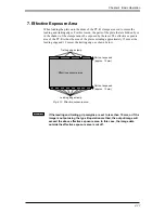
7. Effective Exposure Area
When loading the plate onto the drum of the PT-R, clamps are used to secure the
leading and trailing edges. For this reason, the parts of the plate that are hidden by or
in the shadow of the clamps cannot be exposed by the laser. The effective exposure
area of the PT-R is thus the area of the plate excluding approximately 15 mm at the
leading edge and 12 mm at the trailing edge, as shown below.
CAUTION
!
If the leading and trailing grip margins are set to less than 15 mm, or if the
image is output using the type B operation method, the output image will
exceed the above effective exposure area. In this case, the image data
outside the effective exposure area is cut off.
Effective exposure area
Trailing edge clamp
Part not exposed
(approx. 12 mm)
Part not exposed
(approx. 15 mm)
Leading edge clamp
Fig. 4-15 Effective exposure area
Summary of Contents for PLATE RITE 4300
Page 10: ...x...
Page 11: ...Chapter 1 Ensuring Safety 1 This chapter gives information necessary for safe use of the PT R...
Page 26: ...PT R4300 USERS MANUAL 1 16 End of Chapter 1...
Page 38: ...PT R4300 USERS MANUAL 3 8 End of Chapter 3...
Page 39: ...This chapter explains the basic procedures for operating the PT R Chapter 4 Basic Operation 4...
Page 60: ...PT R4300 USERS MANUAL 4 22 End of Chapter 4...
Page 61: ...This chapter explains the procedures for setting PT R parameters Chapter 5 User Menu 5...
Page 122: ...PT R4300 USERS MANUAL 5 62 End of Chapter 5...
Page 157: ...This chapter explains this typical PT R problem and the solutions Chapter 8 Jamming 8...
Page 163: ...This chapter gives technical information on the PT R Chapter 9 Technical Information 9...

