PT-R4300 USERS MANUAL
5-26
(
)
(
)
(
)
(
)
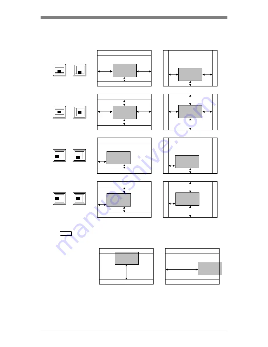
The following diagrams show the relation of the image centering and offset value
settings to the image output position.
NOTE
• When an image is output from the host computer, an error will occur if the image
is moved by an offset setting to the point that it extends beyond the plate size
minus the leading and trailing grip settings.
• If multi-output has been selected in the exposure condition settings, the settings
for image centering in the secondary scanning direction and image offset in the
secondary scanning direction will be ignored.
a
a
a
a
Offset V
Trailing grip
Leading grip
Leading grip
Leading grip
Leading grip
Trailing grip
Trailing grip
Trailing grip
Trailing grip
Trailing grip
Leading grip
Leading grip
Trailing grip
Leading grip
Trailing grip
Leading grip
Offset V
Offset V
Offset H
Offset H
Offset H
Offset H
Offset V
a
a
a
a
b
b
b
b
b
b
b
b
Offset V
Trailing grip
Trailing grip
Leading grip
Leading grip
Offset H
Example:
Fig. 5-31 Relation of image output positions
Summary of Contents for PLATE RITE 4300
Page 10: ...x...
Page 11: ...Chapter 1 Ensuring Safety 1 This chapter gives information necessary for safe use of the PT R...
Page 26: ...PT R4300 USERS MANUAL 1 16 End of Chapter 1...
Page 38: ...PT R4300 USERS MANUAL 3 8 End of Chapter 3...
Page 39: ...This chapter explains the basic procedures for operating the PT R Chapter 4 Basic Operation 4...
Page 60: ...PT R4300 USERS MANUAL 4 22 End of Chapter 4...
Page 61: ...This chapter explains the procedures for setting PT R parameters Chapter 5 User Menu 5...
Page 122: ...PT R4300 USERS MANUAL 5 62 End of Chapter 5...
Page 157: ...This chapter explains this typical PT R problem and the solutions Chapter 8 Jamming 8...
Page 163: ...This chapter gives technical information on the PT R Chapter 9 Technical Information 9...

