background image

Installation Guide

Daintree

®

 Networked Wireless Adapter (WA100-PM)

2

2

4

3

WA100-PM Model Variants

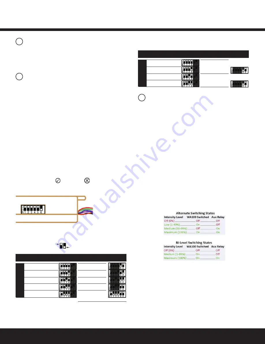
DIP Switch Mode descriptions

DIP Switch settings

The model number WA100 was the original version of the 

adapter and is no longer sold. The 

WA100-PM

 model monitors 

and measures the power consumption of the connected lighting 

load. The WA100-PM reports power measurement data to DCS.

Figure 1: 

DIP switch location

Figure 2: 

DIP Switch Table — See DIP switch Mode 

descriptions for information about each option.

DIP switch settings enable the WA100-PM to operate a

ppropriately for the type of lighting control it provides and 

the type of device(s) to which it is connected and adapting 

for wireless communication. Set DIP switches based only on 

the 

devices that are physically wired to the WA100-PM.

There are two primary adaptation modes to choose from as 

determined by the DIP switch 1 setting.

•  In Light Adapter Mode, the settings are for the type

  of lighting control that is available on the connected

  driver, and/or the sensor type(s) connected to the

 WA100-PM.

•  In the Switch Adapter Mode, settings are for the

  connected switch type and whether the WA100-PM

  is connected to a light.
Configure DIP switch settings only as shown in this instruction. 

Incorrect switch settings will cause unexpected operation.

After you change DIP switch settings, you need to press the blue 

Reset button for 3 seconds to reset the unit. Release the button 

when the green Joined        and red Error        LEDs begin flashing.

Light Adapter Mode
Control Type

On/Off + 0-10V dimming: 

provides On/Off control using its line 

voltage Switched Load connection to the driver(s). It also provides 

0-10V dimming control to the driver(s).

On/Off (no dimming): 

provides On/Off control using its line 

voltage Switched Load connection, and its low voltage digital 

output to an external relay. Note, both outputs are switched at 

the same time in this driver control mode.

Alternate:

 provides On/Off switching for one driver load using its 

line voltage Switched Load connection, and its low voltage digital

output to an external relay to switch a second driver load. This 

allows lighting level control for no load (0%), one or the other of 

the two loads, and both loads (100%). See Figure 13.

Bi-Level:

 provides On/Off switching for one driver with two loads 

using its line voltage Switched Load connection and low voltage 

digital output an external relay to switch the second load. This 

allows lighting level to control for no load (0%), partial load

 (according to driver capability) or full load (100%). See Figure 12.

No Driver (sensors only):

 provides wireless adaptation to 

connected occupancy sensor and/or photosensor only. No 

driver control.

Sensor

To provide wireless adaptation for sensors, set DIP switches 1, 5 & 

6 according to the type(s) of sensors connected to the WA100-PM.

Range Extender

The WA100-PM joins the ZigBee network and acts only as a 

wireless repeater to improve the wireless range and/ or reliability. 

No lights or devices are connected to the WA100-PM.

Occupancy

Photosensor

Both

None

Range Extender*


no light, no sensor

*Valid only with firmware v2.6 or higher

On/Of f + 0-10V dimming

On/Of f (no dimming)

Alternate Switching

Bi-Level

No Driver (sensors only)

SensorSwitches 5 & 6

Mode 

Driver Type Switches 1 to 4

DIP Switch Positions 

Light Adapt

er

OFF

ON

Light + Switch

(driver & switch

are same type)

No Light

(switch only)

Dimming

On/Of f (no dimming)

Alternate Switch

Bi-Level

Light Output

  Switches 5 & 6

Mode

     Switch Type

 Switches 1 to 4

Switch Adapter

Figure 2: 

DIP Switch Table — See DIP switch Mode 

descriptions for information about each option.

Summary of Contents for GE Current WA100-PM

Page 1: ...network and controls lights The WA100 PM is an AC powered device that provides On Off switching as well as 0 10V analog dimming control for LED drivers and ballasts It also provides power for low volt...

Page 2: ...n Off no dimming provides On Off control using its line voltage Switched Load connection and its low voltage digital output to an external relay Note both outputs are switched at the same time in this...

Page 3: ...he Black Hot flying lead and the Red Switched Load flying lead are 14AWG The White Neutral flying lead is 18AWG Low voltage 22AWG flying leads provide for connections to supply low voltage power and c...

Page 4: ...Wireless Adapter WA100 PM 4 Figure 3 Wiring Identification Figure 4 Dimming Light Fixtures 7 Wiring Continued Perform Installation Test Suite 1 DIP Switches Driver Type On Off 0 10V dimming Wired Sens...

Page 5: ...s Occupancy Sensor configuration This configuration allows the WA100 PM to provide automatic On Off switching based on occupancy Set occupancy sensor for minimum time delay 7 Wiring Continued Perform...

Page 6: ...or for minimum time delay Figure 8 Dimming Light Fixture s Photosensor configuration This configuration allows the WA100 PM to provide automatic 0 10V dimming control and to switch light fixtures On O...

Page 7: ...ght Fixture s and Switch configuration This configuration allows the WA100 PM to provide 0 10V dimming control and to switch light fixtures On Off It also provides manual On Off control through a low...

Page 8: ...ching This configuration allows the WA100 PM to alternate in switching separate drivers providing no load 0 partial load according to the driver loading or full load 100 Always connect the smaller pro...

Page 9: ...gure 14 208V 2 Pole Phase to Phase wiring This configuration allows the WA100 PM to provide On Off switching of a branch circuit 7 Wiring Continued OFF ON OFF ON Perform Installation Test Suite 1 DIP...

Page 10: ...gure 15 Switching Contactors This configuration allows the WA100 PM to provide On Off switching control to an external contactor 7 Wiring Continued OFF ON Perform Installation Test Suite 1 DIP Switche...

Page 11: ...V output from the WA100 PM and the Emergency Light Fixture operates at maximum output from the Emergency power circuit Note If the RRU 2 is not installed the Emergency Fixture will dim to minimum beca...

Page 12: ...is included with the WA100 PM Affix this label to the outside of the fixture Choose a standard location so that when someone looks for fixtures containing a WA100 PM they will easily find it Using the...

Page 13: ...e 2 Any Driver Occupancy Sensor 1 Press and immediately release the blue Reset button The red Error LED flashes once then pauses and repeats 2 Check that the connected lights cycle On and Off or cycle...

Page 14: ...the green Joined LED and the red Error LEDs begin flashing Test Suite 4 Continued 4 Operate the switch es connected to the WA100 PM and observe that the lights turn On Off and Dim as expected 5 Press...

Page 15: ...own after the sensor s internal time delay expires Therefore set occupancy sensors for the minimum time delay during the WA100 PM installation The red Error LED is flashing once every second DIP switc...

Page 16: ...lug load circuit Wiring for Combination Plug Load Basic Aux Relay and On Off Light In the wiring diagram below the WA100 PM is used to control both an On Off light and a plug load circuit Plug Load Ap...

Page 17: ...plug load circuit Plug Load Applications Continued Perform Installation Test Suite 1 DIP Switches Driver On Off 0 10V dimming Plug Load On Off Wired Sensor None On 1 2 3 4 5 6 2 3 On OFF ON 0 10V Dim...

Page 18: ...t and a plug load circuit Plug Load Applications Continued Perform Installation Test Suite 1 DIP Switches Driver On Off Plug Load On Off Wired Sensor None On 1 2 3 4 5 6 2 4 On OFF ON 0 10V Dimming ou...

Page 19: ...RECT TYPE DISPOSAL OF USED BATTERIES ACCORDING TO THE INSTRUCTIONS WFA100 PM Input Voltage 120 277VAC 50 60Hz Switched Output 15A driver incandescent 120 277VAC Relay 1hp 120 230VAC switched to Hot Ac...

Reviews: