Installation Guide
Daintree
®
Networked Wireless Fixture Adapter (WFA100-SN)
Sensor (occupancy and photo) wiring lengths above 3m were
not considered for immunity.
This equipment has been tested and found to comply with
the limits for a Class B digital device, pursuant to Part 15 of
the FCC Rules. These limits are designed to provide reasonable
protection against harmful interference in a residential
installation. This equipment generates, uses and radiates radio
frequency energy and, if not installed and used in accordance
with the instructions, may cause harmful interference to radio
communications. However, there is no guarantee that
interference will not occur in a particular installation. If this
equipment does cause harmful interference to radio or television
reception, which can be determined by turning the equipment
off and on, the user is encourage to try to correct the
interference by one or more of the following measures:
• Reorient or relocate the receiving antenna;
• Increase the separation between the equipment
and receiver;
• Connect the equipment into an outlet on a circuit different
from that to which the receiver is connected;
• Consult the dealer or an experienced radio/TV technician
for help.
These instructions do not purport to cover all details or variations in equipment nor to provide for every possible contingency to be met in connection with installation, operation
or maintenance. Should further information be desired or should particular problems arise which are not covered sufficiently for the purchaser’s purposes, the matter should be
referred to GE Current, a Daintree company.
Questions:
Web:
products.gecurrent.com
Phone:
1-866-855-8629
www.gecurrent.com
© 2021 Current Lighting Solutions, LLC. All rights reserved. GE and the GE monogram are trademarks of the
General Electric Company and are used under license. Information provided is subject to change without notice.
All values are design or typical values when measured under laboratory conditions.
DT111 (Rev. 04/22/2021
Input Voltage
120-277VAC, 50-60Hz
Isolated Relay
N/O and N/C contacts Load: 3A@120VAC-
-277VAC
Load Types
Electronic Ballast, General Use
Low Voltage
24VDC; 35mA max
Output
Analog Dimming
22AWG, 600V, UL 1015, plenum rated Max.
Output
recommended length of up to 100’ (30m)
Analog Photosensor
0-10VDC
Input
Analog Input
Photosensor 0-10VDC
Digital Input
Active high occupancy sensor
Radio Properties
2.4 GHz, +8 dBm, Range dependent
on RF propagation variables such
as metal obstacles
Operating
Indoor, dry location
Environment
-13° to +158°F (-25° to +70°C)
Compliance
UL, FCC Part 15, CE
Mounting
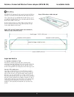
Inside fixture, or enclosure
Dimensions
1.18” W x 0.98” H x 7.03” L
(30mm W x 25mm H x 178.5mm L)
Specifications
CE Warning message
FCC Warning Message
CAUTION
RISK OF EXPOSURE IF BATTERY IS REPLACED BY AN
INCORRECT TYPE. DISPOSAL OF USED BATTERIES
ACCORDING TO THE INSTRUCTIONS.
WFA100
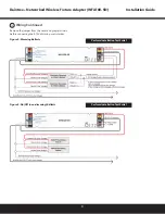
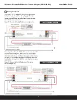
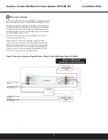
Installation Instructions
Each terminal can accept one conductor only. Connect only
one 24AWG to 16AWG (0.2 -1.5mm2) wire to any terminal
locations showing normal/emergency.
WFA100
8
9
* References to “ballast” include LED drivers, general use loads.


