background image

Installation Guide

Daintree

®

 Networked Wireless Fixture Adapter (WFA100-SN)

4

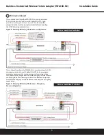
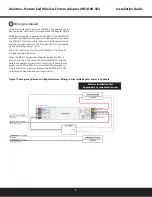
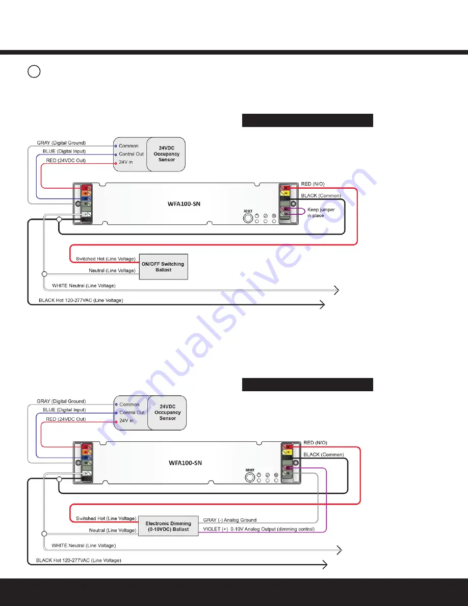
Figure 6: On/Off (non-dimming) Ballast(s), Occupancy 

Sensor configuration

Figure 7: Dimming Ballast(s), Occupancy Sensor configuration

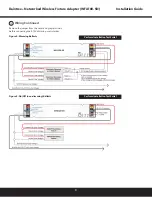
Figure 5: On/Off (non-dimming) Ballasts

Perform Installation Test Suite 2

3

Wiring Continued

This configuration allows the WFA100-SN to provide automatic 

On/Off switching of ballasts and provides an occupancy sensor 

input. Set the occupancy sensor for the minimum time delay.

This configuration allows the WFA100-SN to provide automatic 

0-10V dimming control and to switch ballasts On/Off. It also 

provides an occupancy sensor input. Set occupancy sensor for 

minimum time delay. 

Remove the jumper from the violet and 

gray terminals before connecting the 0-10V dimming control 

wires. Remove the jumper from the blue and gray terminals 

before connecting the occupancy sensor wires.

Perform Installation Test Suite 2

Summary of Contents for GE Current WFA100-SN

Page 1: ...ices that provide On Off switching as well as 0 10V analog dimming control for ballasts and LED drivers The WFA100 SN also provides power and signal connections for low voltage occupancy sensors and p...

Page 2: ...in DCS wireless signals from the WAC to the WFA100 SN determine operation of the light s Design Caution Do not install a wireless adapter such as the WFA100 SN to control an electrical circuit that p...

Page 3: ...FA100 SN 3 Figure 4 Dimming Ballasts Figure 5 On Off non dimming Ballasts Perform Installation Test Suite 1 Perform Installation Test Suite 1 3 Wiring Continued Remove the jumper from the violet and g...

Page 4: ...On Off switching of ballasts and provides an occupancy sensor input Set the occupancy sensor for the minimum time delay This configuration allows the WFA100 SN to provide automatic 0 10V dimming contr...

Page 5: ...On Off It also provides an analog photosensor input 0 10V Remove the jumper from the violet and gray terminals before connecting the 0 10V dimming control wires This configuration allows the WFA100 SN...

Page 6: ...rcuit Regular power is brought into the fixture from an adjacent fixture and connects to the RRU X UM While Regular power is supplied to the RRU X UM the WFA100 SN provides switched On Off power to th...

Page 7: ...e ballast The WFA100 SN also controls dimming to the Regular Fixture and the Emergency Fixture The Emergency Fixture is powered by the Emergency power circuit The 0 10V dimming circuit from the WFA100...

Page 8: ...control device at the time of installation Finding installation issues or device problems earlier saves significant time during the commissioning process Record IEEE Addresses If you have not already...

Page 9: ...tosensor 1 Press and immediately release the Reset button The red Error LED flashes once then pauses and repeats 2 Check that the connected lights cycle On and Off or cycle from maximum to minimum bri...

Page 10: ...ray terminals If connected to an occupancy sensor remove the jumper from the Blue and Gray terminals If not connected to an occupancy sensor be sure the jumper is connected between the Blue and Gray t...

Page 11: ...hould particular problems arise which are not covered sufficiently for the purchaser s purposes the matter should be referred to GE Current a Daintree company Questions Web products gecurrent com Phon...

Reviews: