Installation Guide
Daintree
®
Networked Wireless Fixture Adapter (WFA100-SN)
6
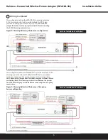
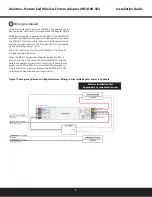
Figure 10: Bypass WFA100 switched power and 0-10V dimming control during power failure
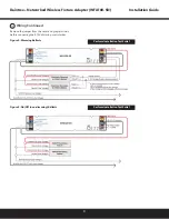
Figure 5: On/Off (non-dimming) Ballasts
3
Wiring Continued
In the wiring diagram below, the WFA100-SN is powered by
the Emergency power circuit.
Regular power is brought into the fixture from an adjacent
fixture and connects to the RRU-X-UM.
While Regular power is supplied to the RRU-X-UM the
WFA100-SN provides switched On/Off power to the
fixtureand controls dimming.
When the RRU-X-UM senses loss of Regular power, it passes
Emergency power directly to the fixture and disconnects the
WFA100-SN switched output. Loss of Regular power to the
RRU-X -UM disables the WFA100-SN dimming controland
the fixture will operate at maximum output.


