Installation Guide
Daintree
®
Networked Wireless Fixture Adapter (WFA100-SN)
7
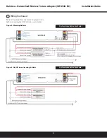
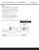
Figure 11: Emergency Fixture and Regular Fixture: Wiring to Dim while Regular Power is Available
3
Wiring Continued
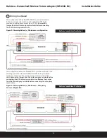
In the wiring diagram below, the WFA100-SN is powered by the
Regular power circuit and is installed inside the Regular Fixture.
While Regular power is supplied to the RRU-2, the WFA100-SN
provides switched On/Off power to the Regular Fixture ballast.
The WFA100-SN also controls dimming to the Regular Fixture
and the Emergency Fixture. The Emergency Fixture is powered
by the Emergency power circuit.
The 0-10V dimming circuit from the WFA100-SN is brought
into the Emergency Fixture.
When the RRU-2 senses loss of Regular power, the RRU-2
disconnects the 0-10V output from the WFA100-SN and the
ballast will operate at maximum output from the Emergency
power circuit. (If the RRU-2 is not installed, the Emergency
Fixture will dim to minimum because the WFA100-SN 0-10V
output shorts when the adapter loses power.)
Perform Installation Test
appropriate to connected sensors


