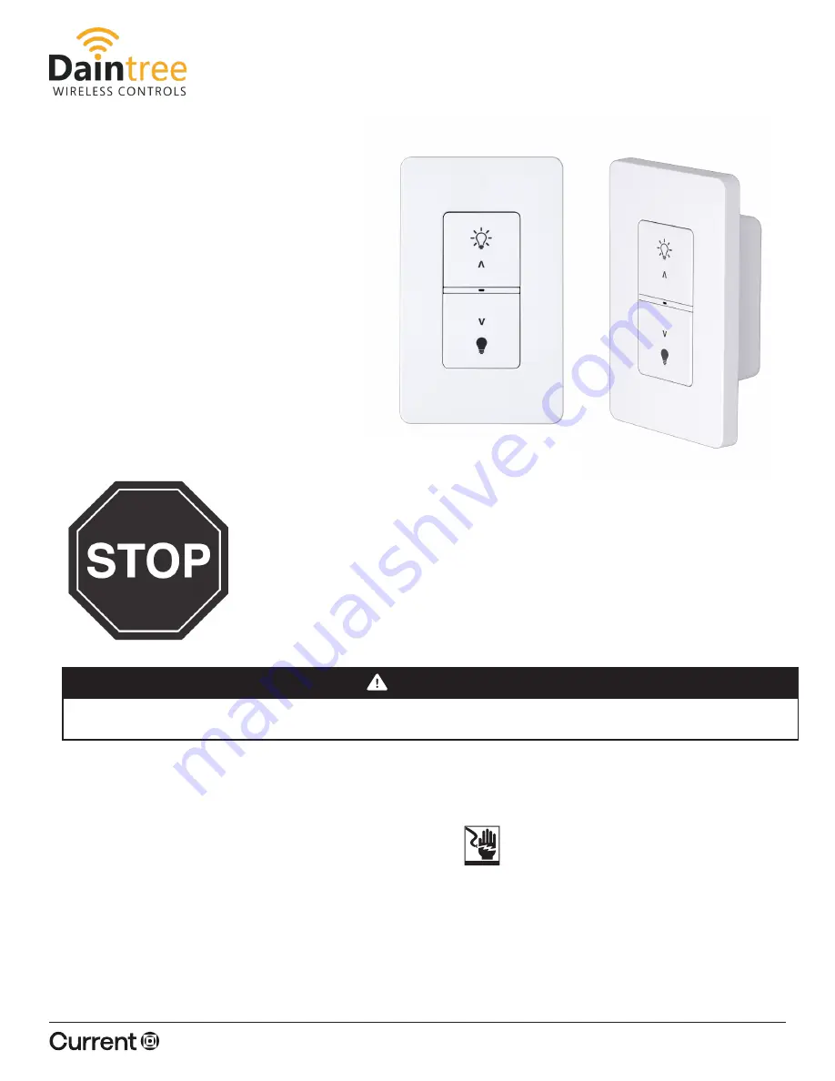
LightOWL® Dual Technology Passive Infrared
and Acoustic Sensors (LODIA)
INSTALLATION INSTRUCTIONS
Page 1 of 8
Rev 04/11/23
WWD2-2_InstallSheet_R01
currentlighting.com
© 2022 HLI Solutions, Inc. All rights reserved. Information and specifications subject to change
without notice. All values are design or typical values when measured under laboratory conditions.
WWD2-2IW
Installation Guide
Product Overview
RISK OF ELECTRIC SHOCK
Disconnect power before servicing or installing product .
WARNING
BEFORE YOU BEGIN
Read these instructions completely and carefully.
Save these instructions for future use.
IMPORTANT
To ensure the product warranty is valid, please ensure
all installation instructions and environmental conditions
for storage and operation are complied with.
Installation to be performed by factory trained or qualified
personnel.
Save These Instructions
Use only in the manner intneded by the manufacturer.
If you have any questions, contact the manufacturer.
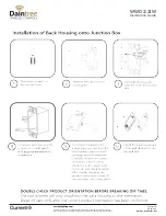
Prepare Electrical Wiring
¥When replacing a line voltage switch, the
power must be off at the branch circuit
breaker. Bypass the line voltage switch to
provide uninterrupted power to the fixtures
and make sure the connection is properly
insulated before installing the wireless switch.
intended
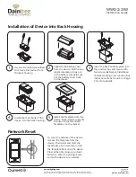
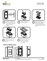
The WWD2-2IW wireless dimmer is a battery powered
in-wall mount switch for use in zonal room control
or as part of a large wireless networked system. The
WWD2-2IW device installs into an existing junction
box to replace an existing switch providing a wire-
less solution that enables dimming and ON/OFF
commands to be delivered to luminaires in its com-
missioned space. The communication with the lumi-
naires or wireless controllers utilizes a secure a reliable
wireless connection which helps minimize installation
cost and complexity.
Electrical Requirements


