background image


[32] 

Rev 4/15/14 


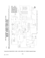
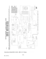
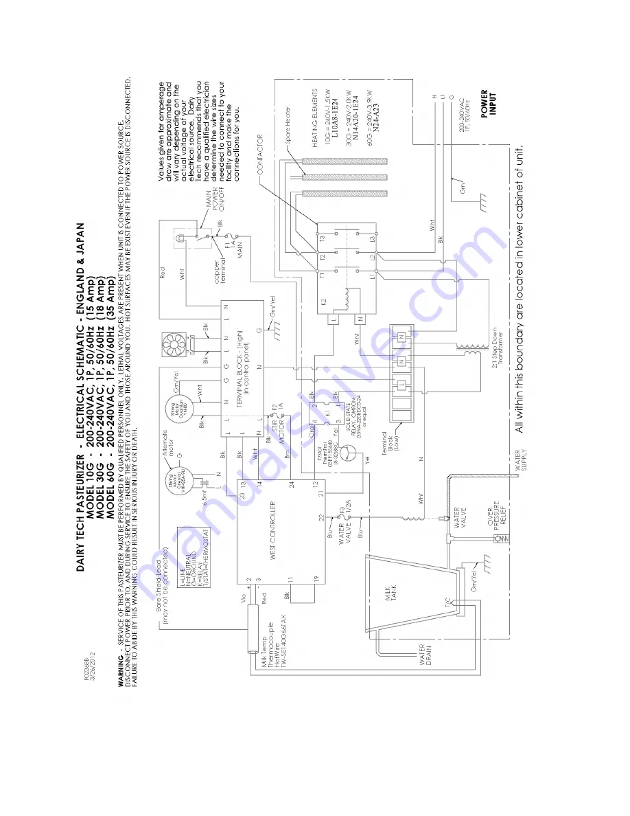
Schematic for Model DT10, 30, 60G – 200 to 240VAC, 1P, 50/60Hz, England & Japan 


Summary of Contents for Platinum Series

Page 1: ...1 Rev 4 15 14 Dairy Tech Inc Service Manual DT10G DT30G DT60G Operator Manual Platinum Series Pasteurizers Models DT10G DT30G DT60G...

Page 2: ...2 Rev 4 15 14 Dairy Tech Inc Service Manual DT10G DT30G DT60G...

Page 3: ...medical ISM radio frequency equipment Group 2 Class A EN 61000 6 2 1999 Electromagnetic Compatibility Generic Standards Immunity for Industrial Environments NOTE 1 This equipment must be installed and...

Page 4: ...ing the DT60G 8 Mounting the Control Panel 8 Mounting the DT10G onto the Base 9 Lid Storage 9 Connecting the Milk Spigot 10 Choosing and Preparing a Location 10 Criteria for Selecting a Location 10 Co...

Page 5: ...rofile 25 Instructions for downloading a new profile to your Dairy Tech Pasteurizer from a USB memory stick 25 Control Configuration 26 HOW TO CHANGE FROM FAHRENHEIT TO CELCIUS 27 IF TEMPERATURE NEEDS...

Page 6: ...MMON SENSE CAUTION AND CAREFULNESS ARE FACTORS WHICH CANNOT BE BUILT INTO THE PASTEURIZER THESE FACTORS MUST BE SUPPLIED BY THE PERSON S INSTALLING MAINTAINING OR OPERATING THE PASTEURIZER Under no ci...

Page 7: ...Surfaces include the lid plumbing fixtures electrical fixtures hoses heater body milk cabinet surfaces draining water and the milk or colostrum Touching these surfaces during operation may result in s...

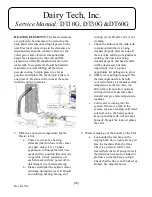
Page 8: ...he DT60G which has side mounting screws to secure the control box to the top of the cabinet The motor shaft must also be attached by inserting it through the side entry of the coupler followed by righ...

Page 9: ...wder coated box and set the DT10G to the side Turn the white box over and move it to the location where you wish to install the machine Lift the pasteurizer and place it on the box so that the sides a...

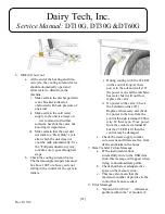
Page 10: ...0vac for control power in models where necessary e Floor space requirements are approx 1 yd 1M f Avoiding extremely drafty areas will improve heating efficiency of the unit g Always have 2 people lift...

Page 11: ...CONNECTIONS SHOULD BE PERFORMED BY AN ELECTRICIAN OR OTHER TRAINED PERSONNEL The receptacle should be sharing minimal usage with other equipment to avoid unexpected outages and tripping of the breaker...

Page 12: ...e Shooting for further information AT FIRST USE OF THE MACHINE The system must be charged with water to prevent damage to the heating elements Once the installation is completed place a couple of gall...

Page 13: ...inate the product with bacteria from the bottom and sides of the bottles Always wear nitrile or latex gloves when handling the milk or colostrum to prevent the spread of pathogens from the skin surfac...

Page 14: ...select a profile that you wish to run then press the return arrow key FOR THE FIRST USE OF THE MACHINE SELECT THE COLOSTRUM COOL ONLY PROFILE FOLLOW OTHER INSTRUCTIONS ON PREVIOUS PAGE You will be as...

Page 15: ...memory remaining or power of outputs LED red lights in top indicate outputs for heating cooling and stirring of the product Main Numbers are the temperatures displayed in F or C The Dairy Tech ProVu c...

Page 16: ...ir instructions What if the milk becomes spoiled before I pasteurize it This condition is fairly common and can happen at times even when the same successful routines have been followed There are spoi...

Page 17: ...ze colostrum NO When done properly colostrum can be successfully pasteurized to eliminate the same pathogens that can be found in the milk They are even more dangerous in colostrum since these bacteri...

Page 18: ...he system checked by a certified electrician before operating c Check the 1amp fuse F1 Make sure there is 115vac to and through the fuse If not replace with appropriate fuse DO NOT REPLACE WITH OVERSI...

Page 19: ...s at the A1 and A2 tabs black and white 16awg wires on the back top of the contactor to see if it is being signaled by the SS relay If there is 115vac signal but no activation of the contactor replace...

Page 20: ...tor is turning during the cycle It should be on during heating timing and cooling cycles Replace if it is not working c Check the bottom of the milk tank to make certain that it is being cleaned prope...

Page 21: ...in the control for the cycle to initiate i During cooling with the 2 LED on the control lit up Is there power to the solenoid valve If the power is on and the machine has water but it will not flow re...

Page 22: ...d or congealed a The most common cause for milk or colostrum to separate or congeal is acidification of the milk caused by two processes i Fermentation of the milk by bacteria will cause the release o...

Page 23: ...failure This will also occur if someone shuts the unit off prior to completion of its assigned cycles and the unit will automatically restart when the toggle switch or power is restored If a long time...

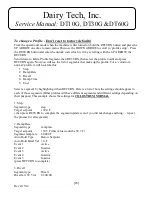
Page 24: ...profiles must individually be changed to Celsius as well This is not automatic for the profiles Decimal Point Position 123 4 Scale Input Range Lo Limit 0 make sure it is 0 when in Celsius Scale Input...

Page 25: ...r has configured your memory stick with the appropriate files so that it can handle data that is usable by the control Remove the memory stick hold the enter button and press the up arrow twice to ret...

Page 26: ...old the RETURN button and press the UP ARROW one time Then use the DOWN ARROW to scroll to configuration menu Press the RETURN button and enter the unlock code which is 10 by scrolling with the UP ARR...

Page 27: ...ine is first turned on hold the RETURN button and press the UP ARROW one time Then use the DOWN ARROW to scroll to configuration menu Press the RETURN button and enter the unlock code which is 10 by s...

Page 28: ...this 1 Step 2 Ramp Rate 3 Dwell 4 Ramp Time 5 End Select a segment by highlighting it then RETURN Here is a list of how the settings should appear in each of those segments Other profiles will have di...

Page 29: ...amp Time Segment type ramp time Target setpoint 90 0 F this is the cool point Segment ramp time 00 00 02 Auto hold type above setpoint Auto hold band value 2 0 F Event 1 Active Event 2 Active Event 3...

Page 30: ...access the controller main menu for milk heater temperature settings as well as process timing follow these steps Accessories Contact Dairy Tech Inc Dairy Tech Inc 34824 CR 29 Greeley CO 80631 Phone...

Page 31: ...31 Rev 4 15 14 Schematic for Model DT10 30 60G 200 to 240VAC 1P 50 60Hz USA Domestic...

Page 32: ...32 Rev 4 15 14 Schematic for Model DT10 30 60G 200 to 240VAC 1P 50 60Hz England Japan...

Page 33: ...33 Rev 4 15 14 Schematic for Model DT10 30 60G 400VAC 3P Europe...

Page 34: ...34 Rev 4 15 14 NOTES...

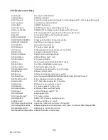
Page 35: ...er 220vac 30amp dryer cord ME CordGrip1 1 power cord grip ME Fan 3 125 axial fan 115VAC 34CFM 12 leads ME FanFilter Fan Filter Washable Aluminum ME FuseHold fuse holder 16a 1 4 x 1 4 ME MotorGear120 r...

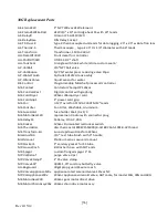
Page 36: ...r 220vac 30amp dryer cord ME CordGrip1 1 power cord grip ME Fan 3 125 axial fan 115VAC 34CFM 12 leads ME FanFilter Fan Filter Washable Aluminum ME FuseHold fuse holder 16a 1 4 x 1 4 ME MotorGear120 re...

Page 37: ...Spigot custom flanged spigot 1 SS MP ValRelief purge valve 4 psi MP ValveClamp1 1 SS valve clamp MP ValveSS1 304SS 1 25 sanitary butterfly valve JE element 24 cartridge heating element 3900watt 3 4 di...

Page 38: ...38 Rev 4 15 14...

Reviews: