background image

Installation and Maintenance

Service Manual

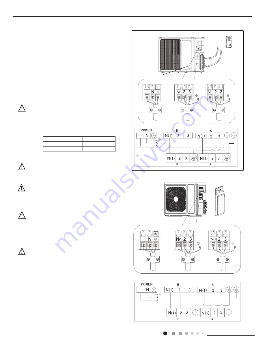
LN

To the power supply

To unit B

Power cord

To unit A

connecting

    cable

L

L

connecting

    cable

Handle

Handle

Front

side plate

LN

To the power supply

To unit B

Power cord

To unit A

connecting

    cable

L

L

connecting

    cable

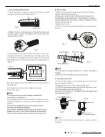
1. Remove the handle at the right side plate of the outdoor
unit (one screw).
2. Remove  the  cable  clamp,  connect  the  power  connection
cable  with  the  terminal  at  the  row  of  connection  and  fix  the

FRQQHFWLRQ7KH¿WWLQJOLQHGLVWULEXWLQJPXVWEHFRQVLVWHQWZLWK

the indoor unit. terminal of line bank. Wiring should meet that of 
indoor unit.
3. Fix power connection wire by wire clamp.

 (QVXUHZLUHKDVEHHQ¿[HGZHOO

5. Install the handle.

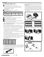
Including  an  air  switch  with  suitable  capacity,please  note 
the following table. Air switch should be included  magnet 
buckle  and  heating  buckle  function,  it  can  protect  the 
circuit-short and overload. (Caution: please do not use the 
fuse only for protect the circuit)

Wrong wire connection may cause malfunction of

VRPHHOHFWULFFRPSRQHQWV$IWHU¿[LQJFDEOHHQVXUH

WKDWOHDGVEHWZHHQFRQQHFWLRQWR¿[HGSRLQWKDYH

some space.

Electrical Connections

..

An  all-pole  disconnection  switch  having  a  contact 
separation of at least 3mm in all pole should be connected 

LQ¿[HGZLULQJ

The connection pipes and the connectiong wirings
of the unit A and unit B must be corresponding to
each other respective.

The appliance shall be installed in accordance with
national wiring regulations.

1RWHWKHDERYH¿JXUHVDUHRQO\LQWHQGHGWREHDVLPSOH

diagram of the appliance and may not correspond to the
appearance of the units that have been purchased.

.

.

Air-conditioner

Air switch capacity

.

10A

.

10A

Summary of Contents for DS-9KIDB

Page 1: ...Service Manual Models ASD9U2I DN ASD912UI DN...

Page 2: ...5U1 Throttling Method Electron expansion valve Cooling Operation Ambient Temperature Range O C 18 43 Heating Operation Ambient Temperature Range O C 15 24 Condenser Material Aluminum Fin copper Tube C...

Page 3: ...Additional Gas Connection Pipe Length m 10 10 Connection Pipe Gas Additional Charge g m 20 20 Outer Diameter of Liquid Pipe GREE Allocation Metric mm Outer Diameter of Gas Pipe GREE Allocation Metric...

Page 4: ...6 m3 K 550 500 430 300 550 480 410 290 HKXPLGLI LQJ 9ROXPH K 0 8 1 4 Indoor Unit Model of Indoor Unit 6 6 3URGXFW RGH RI QGRRU 8QLW DQ 7 SH URVV RZ URVV RZ LDPHWHU HQJWK mm DQ 0RWRU RROLQJ 6SHHG 6 0...

Page 5: ...Technical Information Service Manual Outline Dimension Diagram Indoor Unit Unit mm Models W H D W1 W2 W3 09 12K 773 250 185 131 462 180 D H W 75 35 55 W3 W2 W1 55 35 75...

Page 6: ...anual 3 Outline Dimension Diagram 892 341 396 963 560 700 368 Unit mm 12 Technical Information Service Manual 3 Outline Dimension Diagram 892 341 396 963 560 700 368 Unit mm 12 Technical Information 8...

Page 7: ...ease refer to the actual models This is a general use remote controller it could be used for the air conditioners with multifunction For some function which the model doesn t have if press the corresp...

Page 8: ...m AUTO COOL DRY FAN and HEAT as the following AUTO COOL DRY FAN HEAT Note Only for models with heating function This button is used for setting Fan Speed in the sequence that goes from AUTO to then ba...

Page 9: ...d buttons simultaneously 3s to lock or unlock the keypad If the remote pressing any button blinks three times controller is locked is displayed In this case Combination of and buttons About lock About...

Page 10: ...me models Replacement of batteries in remote controller Emergency operation If remote controller is lost or damaged please use auxiliary button to turn on or turn off the air conditioner When the air...

Page 11: ...t adequately grounded The grounding wire can t be used for other purposes 6 Must apply protective accessories such as protective boards cable cross loop and wire clip 7 The live wire neutral wire and...

Page 12: ...tape 4 Electroprobe 7 Electronic leakage detector 10 Pipe pliers pipe cutter 2 Screw driver 5 Universal meter 8 Vacuum pump 11 Pipe expander pipe bender 3 Impact drill drill head electric drill 6 Tor...

Page 13: ...e the bound pipes pass through the wall hole and then connect outdoor unit Neaten the pipes Vacuum pumping and leakage detection Check after installation and test operation Finish installation Note th...

Page 14: ...o the wall At least 250cm At least 15cm At least 300cm Space to the obstruction Space to the ceiling Space to the obstruction At least 15cm At least 15cm Space to the wall Space to the wall At least 2...

Page 15: ...LW SOHDVH QRWH WKH IROORZLQJ WDEOH LU VZLWFK VKRXOG EH LQFOXGHG PDJQHW EXFNOH DQG KHDWLQJ EXFNOH IXQFWLRQ LW FDQ SURWHFW WKH FLUFXLW VKRUW DQG RYHUORDG DXWLRQ SOHDVH GR QRW XVH WKH IXVH RQO IRU SURWHF...

Page 16: ...H SRVLWLRQ RI SLSLQJ KROH VKRXOG EH D OLWWOH ORZHU WKDQ WKH ZDOO PRXQWHG IUDPH V VKRZ LQ LJ 5 Connect the Pipe of Indoor Unit LP WKH SLSH MRLQW DW WKH FRUUHVSRQGLQJ EHOOPRXWK V VKRZ LQ LJ 3UHWLJKWHQLQ...

Page 17: ...QJ FRYHU DQG WKHQ WDNH GRZQ WKH FRYHU V VKRZ LQ LJ 8 Bind up Pipe LQG XS WKH FRQQHFWLRQ SLSH SRZHU FRUG DQG GUDLQ KRVH ZLWK WKH EDQG V VKRZ LQ LJ 5HVHUYH D FHUWDLQ OHQJWK RI GUDLQ KRVH DQG SRZHU FRUG...

Page 18: ...apacity please note the following table Air switch should be included magnet buckle and heating buckle function it can protect the circuit short and overload Caution please do not use the fuse only fo...

Page 19: ...d 3 way valves 2 Unscrew and remove the cap from the service valve 3 Connect the vacuum pump hose to the service valve 4 Operate the vacuum pump for 10 15 minutes until an absolute vacuum of 10 mm Hg...

Page 20: ...NLQJ XS DQG PRYLQJ WKH XQLWV RX PXVW EH JXLGHGE WUDLQHG DQG TXDOL HG SHUVRQ Ensure that the recommende dspace is left around the appliance 30cm Space to the cover or above 30cm 50cm Air inlet side or...

Page 21: ......

Reviews: