background image

FMCD-04

FMCD-06

FMCD-12

FMCD-15

FMCD-18

FMCD-20

FMCD-24

FMCD-30

SPLIT

F

MCD - ECM MOTOR

Serie

F

MCD - ECM MOTOR

Edition

R00

Models

INSTALLATION AND MAINTENANCE MANUAL

Summary of Contents for FMCD-04

Page 1: ...FMCD 04 FMCD 06 FMCD 12 FMCD 15 FMCD 18 FMCD 20 FMCD 24 FMCD 30 SPLIT FMCD ECM MOTOR Serie FMCD ECM MOTOR Edition R00 Models INSTALLATION AND MAINTENANCE MANUAL...

Page 2: ...ge in the manufacturing of our products Throughout the production process we maintain strict control starting with our extensive resources in research and development through to the design and manufac...

Page 3: ...onnections with Valve 22 C Maintenance 23 C 1 Opening and Closing of Lift Up Grille Cover 23 C 2 Front Cover Assembly Removal 23 C 3 Air Vent and Water Purge Valves 23 C 4 Wiring Connections 23 D Cont...

Page 4: ...ster Slave Communication Method 42 E 1 4 Unit Network Wiring Scheme 43 E 2 Open Modbus Protocol 44 F Control Specification Flexible Function PCB FLEXI Type Control 47 F 1 I O Port Definitions 47 F 2 W...

Page 5: ...TOTAL Complete function onboard PCB with integrated group control functionality FLEXI Flexible function onboard PCB with louver and zone control functionality V 2 Pipe System 04 See General Specifica...

Page 6: ...ciency and quiet operation Filters washable easy to remove fine mesh air filters are standard to all high wall models Tabs located on the front of the unit can be unsnapped allowing the filter to be e...

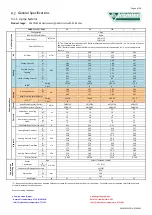
Page 7: ...nd Sound PressureLevel Outlet dB A 34 29 24 39 31 26 40 33 28 45 34 31 Sound Power Level Outlet e 42 38 33 48 40 35 49 42 37 54 43 40 Electrical Power input in cooling modee H W 13 18 13 22 M 10 13 10...

Page 8: ...et dB A 49 44 37 47 39 36 47 44 37 50 47 40 Sound Power Level Outlet e 58 53 46 56 48 45 56 53 46 58 56 49 Electrical Power input in cooling modee H W 30 30 40 50 M 20 20 30 40 L 13 15 19 25 Power inp...

Page 9: ...5 230 680 2 22 4 7 FMCD 18 357 680 2 34 5 7 FMCD 20 378 845 2 36 6 7 FMCD 24 378 845 2 36 6 7 FMCD 30 378 845 2 36 6 7 Dimensional Drawings Dimensional drawing for FMCD 04 06 12 15 18 ECM Model Unit D...

Page 10: ...awing for FMCD 20 24 30 ECM Model Unit Dimensions mm A B C D E F G FMCD 20 24 30 90 1050 51 90 15 73 74 Model Unit Dimensions mm a b c d e f g h FMCD 20 24 30 215 52 30 32 235 310 58 13 Model Unit Dim...

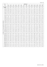
Page 11: ...43 5 36 9 30 8 315 0 Hz 26 0 23 3 21 8 35 2 25 6 22 1 34 0 25 0 22 4 40 9 30 5 25 7 45 0 40 4 34 3 400 0 Hz 33 0 26 4 21 3 39 9 32 0 26 2 39 7 32 3 25 8 46 2 36 2 31 7 50 5 45 1 38 0 500 0 Hz 32 0 24...

Page 12: ...3 46 0 315 0 Hz 11 7 12 9 11 6 13 6 24 1 21 7 25 3 31 5 32 9 37 1 39 3 42 6 45 4 47 2 400 0 Hz 13 7 14 0 12 7 15 8 22 8 26 4 31 5 35 7 38 4 40 1 43 7 46 2 49 6 52 5 500 0 Hz 15 0 15 4 14 3 16 0 21 7 2...

Page 13: ...250 0 Hz 39 3 32 6 28 4 39 7 38 5 34 0 41 4 39 8 34 0 315 0 Hz 40 0 42 4 36 7 43 9 39 6 41 4 46 4 43 2 41 4 400 0 Hz 42 6 38 7 34 8 46 6 42 8 39 5 50 1 46 1 39 5 500 0 Hz 43 6 40 5 35 8 47 8 45 0 40 6...

Page 14: ...3 315 0 Hz 13 8 12 7 15 0 18 3 19 2 22 7 29 4 36 2 40 0 36 5 40 9 43 2 46 0 46 9 400 0 Hz 15 3 15 6 15 6 17 1 21 7 25 9 31 0 33 9 38 2 41 0 44 3 46 1 49 1 51 1 500 0 Hz 17 3 15 9 16 2 19 6 19 9 26 0 3...

Page 15: ...y 3 Way Valve Body Valve Code valve body ON OFF thermoelectric actuator Valve Body Dimensions mm DN A B C D SGS14HFCA 23020101 D15 G1 2 52 47 19 5 63 Valve Code valve body ON OFF thermoelectric actuat...

Page 16: ...R 16 24B DR 15B 24B Normal closed Normal closed Normal closed Voltage 230Vac 24Vac 24Vac Working force 90 125N 90 125N 90 125N Time 4 5min 4 5min 4 5min Power 3W 3W 3W Full stroke 3 5mm 3 5mm 5 0mm Im...

Page 17: ...est the metal bracket for fixing the drain pump and drain pump kits can be offered and preinstalled as optional Please consult our sales representatives for these optional accessories Sauermann conden...

Page 18: ...an coil unit should be performed by qualified service personnel only This appliance is not intended for use by persons including children with reduced physical sensory or mental capabilities or person...

Page 19: ...clearance for maintenance and servicing is as shown above All dimensions shown in mm 5 The unit should be installed higher than eye level 6 Avoid installing the unit with direct sunlight 7 The signal...

Page 20: ...Page 19 of 58 SK2019 FMCD V ECM 001 Mounting Plate Dimensions FMCD 04 06 12 15 18 ECM FMCD 20 24 30 ECM All dimensions shown in mm...

Page 21: ...above figure or by means of gradiometer Failed to follow this may cause water to drip indoors and create atypical noise 4 Fix the mounting plate by means of expansion screws or tapping screws Condens...

Page 22: ...the hooks of the mounting plate Drainage Piping Works 1 Install the drain hose so that it slopes downward slightly for free drainage Avoid installing it as shown in the below illustrations marked with...

Page 23: ...Page 22 of 58 SK2019 FMCD V ECM 001 Pipe Connections with Valve Pre assembly Complete Assembly Flexible hose Valve body with actuator 1 2 gasket Coil connector...

Page 24: ...ront cover and pull the entire assembly out and up towards you Air Vent and Water Purge Valves 1 After connecting the water inlet and outlet pipes to the main supply lines turn on the main breaker and...

Page 25: ...en DIPB SW1 0 Electrical heater safety switch EH Voltage free NC The contact is closed before the EH is turned on Power input Phase L1 Power supply to the PCB and all the loads connected to the voltag...

Page 26: ...ve configuration 0 no valve 1 with valve SW4 preheat setting 0 36C 1 28C SW5 SW6 S3 jump RPM selection L N Power supply VALVE1 230V on off valve output VALVE2 230V on off valve output HEAT Electrical...

Page 27: ...ipe 4 pipe configuration selection SW3 Thermoelectric valve configuration selection 2 pipe system only SW4 Pre heat protection temperature selection SW5 SW6 brushless DC fan motor configuration Defaul...

Page 28: ...IPA S1 Model SW7 SW8 Model setting 0 0 Cool Heat 0 1 Cool Heat booster heater 1 0 Cooling only 1 1 Cool primary heater 7 High Wall Unit ON OFF There are 3 ways to turn the system on or off a By the ON...

Page 29: ...n speed can be adjusted to low medium and high HEAT MODE Without Electrical Heater a MTV2 AUX2 and electric heater are always off b If Tr Ts 1 C or 4 C if economy contact is activated then heat operat...

Page 30: ...setting b If Ti1 38 C or 30 C is selected by DIPB S2 position SW4 then MTV1 and AUX1 are turned on indoor fan runs at set speed c If the indoor coil temperature sensor is damaged then the pre heat ti...

Page 31: ...ccording to the following i If the coil temperature sensor Ti1 36 C then MTV1 AUX1 and fan turn on or off according to HEAT mode ii If Ti1 36 C then MTV1 AUX2 and fan turn on or off according to COOL...

Page 32: ...e heater AUX1 AUX2 MTV1 and MTV2 are turned off b Indoor fan speed can be adjusted to low medium and high HEAT MODE Without electrical heater a MTV1 MTV2 AUX2 and heater are always off b If Tr Ts 1 C...

Page 33: ...at medium speed If indoor fan runs at medium or high speed then it will run at set speed b If Ti1 5 C for 2 minutes then AUX2 is turned on Indoor fan runs at set speed OVER HEAT PROTECTION OF INDOOR C...

Page 34: ...16 30 C e Indoor fan speed can be adjusted to low medium high and auto f When turned on MTV2 requires 30 seconds before it is fully open g When turned off MTV2 requires120 seconds before it is fully c...

Page 35: ...then MTV2 and AUX1 are turned on Indoor fan remains on and runs at set speed c If the indoor coil temperature sensor is damaged then the protection mode will be overridden and the unit will work accor...

Page 36: ...perature The controller adjusts the motor signal input from 0 to 5 VDC by PID calculation every 10 seconds The air flow is adjusted from 15 to100 Louver For remote handset Whenever the indoor fan is r...

Page 37: ...more than 500RPM When electrical heater is ON electrical heater safety switch is opened for 1 second or EC motor RPM is lower than Modbus 310000 setting EH will be turned off immediately and report an...

Page 38: ...nks 3 times stops for 3s E3 Room sensor unplugged or damaged 1 Check if Tr plug is connected or not 2 Check if sensor s resistance is correct or not Indoor coil sensor 1 failure Green LED blinks 4 tim...

Page 39: ...15 times stops for 3s Check unit 15 communication plug and fix it Unit 16 failure RED LED blinks 16 times stops for 3s Check unit 16 communication plug and fix it Unit 17 failure RED LED blinks 17 tim...

Page 40: ...t to Set Master Control Unit 1 Connect all the units PCBs according to the wire color and type of connector 2 Select the master unit by setting DIPA S1 SW6 to ON 1 in the PCB 3 Ensure the DIPA S1 SW6...

Page 41: ...ommunication plug A B A B is printed on the main PCB When you connect the wires please ensure connection of A to A and B to B 3 Connection wire i If the total length of wire is more than 1000m please...

Page 42: ...e contact by using a multimeter 3 Check 1 and 2 3 and 4 5 and 6 to be sure the connections are correct 4 If the resistance between two wire contacts is too high please check and reconnect the wire con...

Page 43: ...DIPA S1 SW4 DIPA S1 SW3 DIPA S1 SW2 DIPA S1 SW1 Unit No Remark 1 0 0 0 0 0 01 Master 0 0 0 0 0 1 02 Slave 0 0 0 0 1 0 03 Slave 0 0 0 0 1 1 04 Slave 0 0 0 1 0 0 05 Slave 0 0 0 1 0 1 06 Slave 0 0 0 1 1...

Page 44: ...Page 43 of 58 SK2019 FMCD V ECM 001 Unit Network Wiring Scheme Wiring diagram for a master slave network connection...

Page 45: ...used to test unit Valid Error code table Error code Description Definition 01 01H Invalid commands Received commands beyond valid commands 02 02H Invalid data address Data addresses beyond valid data...

Page 46: ...alibration wired wall pad and set timer function Minute 300008 W Calibration wired wall pad and set timer function Second 300009 W Calibration wired wall pad and set timer function Hours in Timer on 3...

Page 47: ...d Bit7 Electrical heater failure Bit8 Motor1 Error Bit9 Motor2 Error Bit10 System parameters error Bit11 Anti frozen error Bit12 Reserved Bit13 Reserved Bit14 Reserved Bit15 Reserved Fan speed status...

Page 48: ...loads connected to the voltage outputs Neutral N Power supply to the PCB and all the loads connected to the voltage outputs Earth GND Power supply to the PCB and all the loads connected to the voltag...

Page 49: ...EC m otor output CN4 CN5 Electrical heat on off contact X DIS Led display EC M OTOR 0 10VDC INPUT Lo M Hi V1 valve signal L N L phase to therm ostat custom er care N com m on to therm ostat custom er...

Page 50: ...ode State Description SW1 0 PCB configured for 0 5VDC modulating signal input 1 PCB configured for 0 10VDC modulating signal input MODEL SW2 SW3 SW4 Hi Med Low FMCD 04 0 0 0 700 600 500 FMCD 06 0 0 1...

Page 51: ...lower than 300RPM EH relay is turned OFF at once and report error code 6 Low Temperature Protection of Indoor Coil in Winter This is frost protection for when the unit is off to prevent water in the...

Page 52: ...its settings are automatically sent to the slave units Auto Cool Heat operation will be applicable in 4 pipe system only Swing function is not applicable European version only uses degree C setting Sw...

Page 53: ...f 58 SK2019 FMCD V ECM 001 Wired Wall Pad Controller Day display Mode display Temperature display Fan speed display Timer display Real Time display Master Slave Button display Network icon Sleep icon...

Page 54: ...timer affects the local unit only The system supports ON OFF timer settings for each day of the week Press twice to enter Timer setting interface and timer icon is on When ON blinks press to set timer...

Page 55: ...9 ON OFF setting Press to turn on or off the unit 10 Temperature unit setting Press and at the same time to change temperature unit between Celsius and Fahrenheit 11 Network control Only master unit c...

Page 56: ...er Press to exit parameter checking interface Parameters shown below Temp area Time area C0 Return air temperature C1 Indoor coil 1 temperature C2 DIP switch setting C3 Indoor coil 2 temperature 14 Er...

Page 57: ...6 14 69 15 05 15 41 17 79 8 83 17 86 64 17 14 03 14 37 14 7 16 75 39 78 53 81 76 18 13 41 13 72 14 03 15 71 26 74 18 77 19 19 12 81 13 1 13 4 14 67 37 70 1 72 9 20 12 24 12 52 12 79 13 63 73 66 26 68...

Page 58: ...9284 0 9697 1 012 52 3 225 3 326 3 43 89 0 8998 0 9401 0 9818 53 3 105 3 204 3 305 90 0 8721 0 9115 0 9522 54 2 99 3 086 3 185 91 0 8455 0 8839 0 9237 55 2 88 2 974 3 07 92 0 8198 0 8573 0 8961 56 2 7...

Page 59: ...fuse on board Place in the ON position Check the room control Check fan motor Filter clogged Air flow obstructed Room control regulation Incorrect water temperature Air present Insufficient output Cle...

Page 60: ...Eurofred S A Marqu s de Sentmenat 97 08029 Barcelona www eurofred es...

Reviews: