Page 51 of 62
SK2014
‐
SON
‐
002
‐
TechMnl
‐
FMCD
‐
003
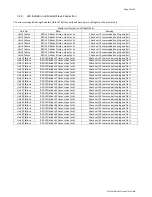
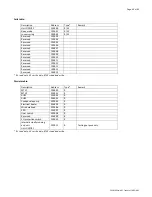
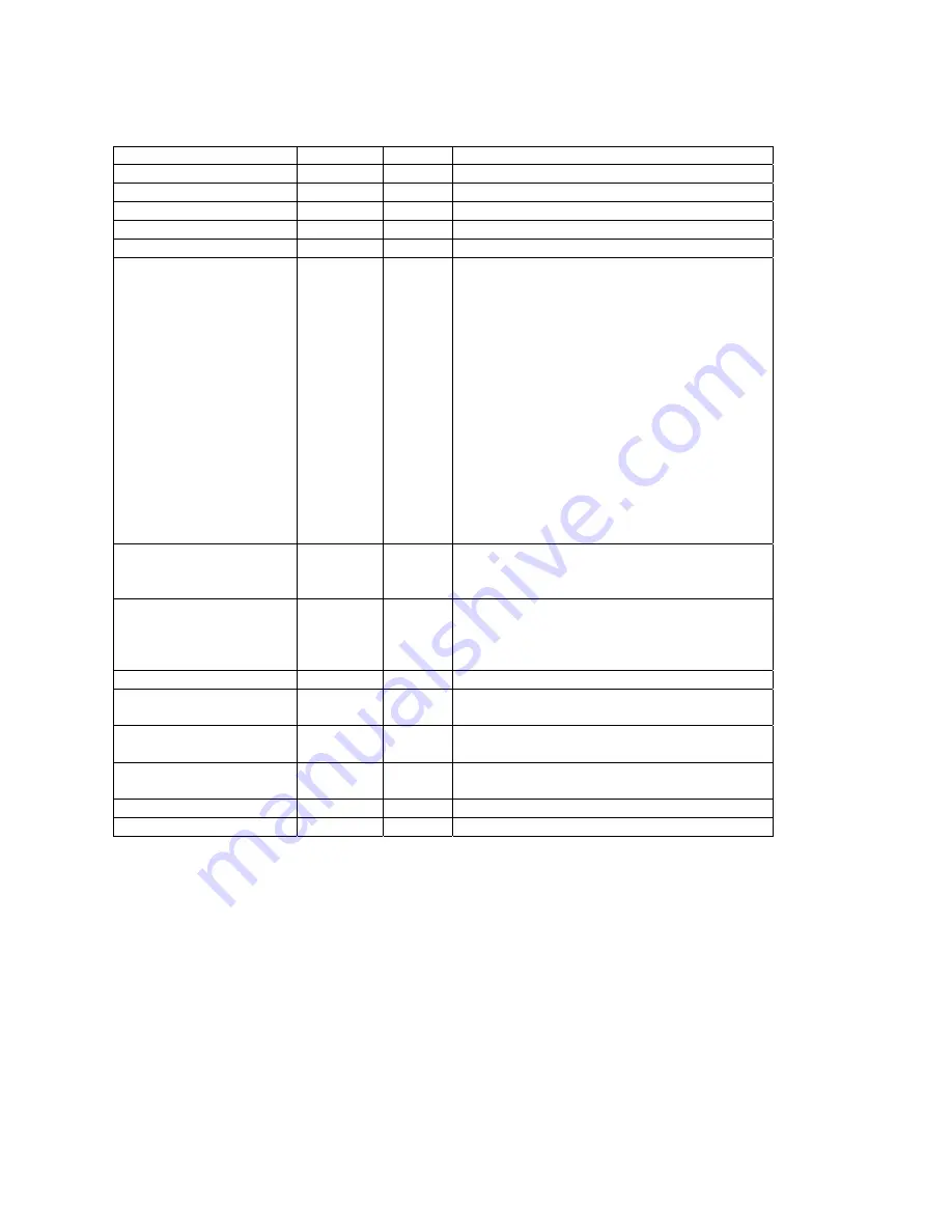
Input
Register
table:
Description
Address
Type*
Remark
Dip
switch
1
status
400000
R
Dip
switch
2
status
400001
R
Room
temperature
sensor
400002
R
Ti1
temperature
sensor
400003
R
Ti2
temperature
sensor
400004
R
Error
code
400005
R
Bit0
=
Room
temperature
sensor
error
Bit1
=
Ti1
temperature
sensor
error
Bit2
=
Ti2
temperature
sensor
error
Bit3
=
Float
switch
error
Bit4
=
Indoor
coil
low
temperature
protection
Bit5
=
Indoor
coil
over
heat
protection
Bit6
=
Reserved
Bit7
=
Electrical
heater
failure
Bit8
=
Motor1
Error
Bit9
=
Motor2
Error
Bit10
=
System
parameters
error
Bit11
=
Reserved
Bit12
=
Reserved
Bit13
=
Reserved
Bit14
=
Reserved
Bit15
=
Reserved
Fan
speed
status
400006
R
Low
=
04(H)
Medium
=
02(H)
High
=
01(H)
Mode
status
400007
R
Cooling
mode
=
01(H)
Dehumidify
mode
=
02(H)
Fan
mode
=
04(H)
Heating
=
08(H)
Setting
temperature
status
400008
R
Testing
only
Room
temperature
in
wall
pad
status
400009
R
Room
temperature
in
main
PCB
status
400010
R
Unit
type
400011
R
4
‐
pipe
=
03,
2
‐
pipe
=
02
This
setting
is
configured
by
dip
switch
EC
motor
1#
RPM
400012
R
EC
motor
2#
RPM
400013
R
*
R
=
read
only,
W
=
write
only,
R/W
=
read
and
write.
Remarks:
The
above
protocol
address
is
Base
0
.
Summary of Contents for FMCD*ECM series
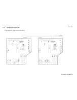
Page 11: ...Page 11 of 62 Dimensional drawing for FMCD 20 24 ECM All dimensionsshown in mm ...
Page 21: ...Page 21 of 62 SK2014 SON 002 TechMnl FMCD 003 C 1 3 Wiring Diagram SK NCFMCD 001 ...
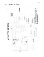
Page 45: ...Page 45 of 62 SK2014 SON 002 TechMnl FMCD 003 C 4 2 Wiring Diagram SK NCFMCD 002 ...
Page 62: ...Page 62 of 62 SK2014 SON 002 TechMnl FMCD 003 ...

