background image

Installation of Indoor Unit  

Installation of Indoor Unit  

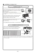
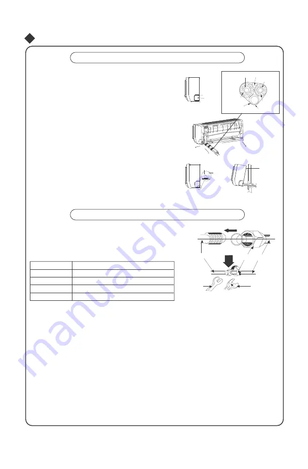
● The piping can be output from right, right rear, left or left rear. 

1. When routing the piping and wiring from the left or right side of 
indoor unit, cut off the tailings from the chassis when necessary 
(As shown in Fig.7) 
 (1) Cut off tailing 1 when routing the wiring only; 
 (2) Cut off tailing 1 and tailing 2 when routing both the wiring and  
       piping.  

2. Take out the piping from body case; wrap the piping, power 
cords, drain hose with the tape and then make them pass 
through the piping hole. (As shown in Fig.8)  

3. Hang the mounting slots of the indoor unit on the upper hooks 

of the mounting plate and check if it is firm enough.


(As shown in Fig.9)  

4. The installation site should be 250cm or more above the floor. 

Liquid side piping  

Tailing 2  

Gas side  
piping insulation

Tailing 1  

Liquid side  

Piping insulation  

Fig.7  

Finally wrap it with tape  

Water drainage pipe  

Left rear

Right  

Right rear 

Fig.8  

Fixing hook  

Mounting  

baord  

Mounting 

plate  

Fig.9  

Installation of Connection Pipe  

1. Align the center of the pipe flare with the related valve.

2. Screw in the flare nut by hand and then tighten the nut with 

spanner and torque wrench by referring to the following:  

Indoor unit piping  

Taper nut   Piping  

Tightening torque, approximate (N·m)  

Tube diameter  

14 ~ 18 N·m (140-180 kgf.cm)  

Ф 6.35 (1/4”)  
Ф 9.52 (3/8”)  

34 ~ 42 N·m (340-420 kgf.cm)  

Spanner  

Torque  
wrench  

Ф 12.7 (1/2”)  

49 ~ 61 N

·

m (490-610 kgf.cm)  

Ф 15.88 (5/8”)  

68 ~ 82 N

·

m (680-820 kgf.cm)  

NOTE: Connect the connection pipe to indoor unit at first and then to outdoor unit. Handle piping bending 
with care. Do not damage the connection pipe. Ensure that the joint nut is tightened firmly, otherwise, it 

may cause leakage.  

- 24 -  

Left

External connection

electric wire

Gas side pipe

Summary of Contents for HS-18UIEK

Page 1: ...u for choosing Residential Air Conditioners please read this owner s manual carefully before operation and retain it for future reference Owner s Manual Residential Air Conditioners MODEL HS 18UIEK HO...

Page 2: ...tands for the items should be forbidden The products in this manual may be different with the real one according to different models some models have displayer and some models without displayer the po...

Page 3: ...se it may cause electric shock or fire Otherwise it may cause electric shock Otherwise it may cause fire due to overheating of power cord Before cleaning the air conditioner please turn off the air co...

Page 4: ...outlet Do not keep windows and doors open for a long time during operation Keep combustible materials at least 1m away from the units It will result in insufficient performance It will result in insuf...

Page 5: ...nds or objects into the air inlet or outlet Do not expose animals orplants directly to the air flow It may cause an accident It may have a detrimental effect on them Do not expose yourself to cold air...

Page 6: ...g heating efficiency The air conditioner may stop operation during auto defrosting operation During auto defrosting the fan motors of indoor unit and outdoor unit will stop During defrosting the indoo...

Page 7: ...rheat Setting temperature at a moderate level helps energy saving Cover windows with a blind or a curtain Blocking sunlight and air from outdoors is favorable for cooling heating Clean air filters onc...

Page 8: ...t Air in 2 6 5 Air out 3 4 The icons displayed 1 Cool Dry Heat Power Set temp 2 Front panel Outdoor unit Air in 7 8 Air out 6 1 Remote control 3 Filter 4 Guide louver 5 Wall pipe 6 Bind tape 7 Connect...

Page 9: ...can be set up signal blink and display Within 5 seconds the value can be adjusted by pressing or button if continuously press this button for 2 seconds above in every 0 5 seconds the value on ten plac...

Page 10: ...ure can be set up continuously press this button and hold for two seconds the re lative contents can quickly change until unhold this button and send the order that the C F signal will be displayed al...

Page 11: ...e one place of minute then the one place is constant ten num bers change in the tens place of minute at 2 5 seconds speed and carry During 5s blink press the Timer On button the timer setting succeeds...

Page 12: ...utton can realize the ON and OFF of TURBO function Introduction for special function About X FAN function This function indicates that moisture on evaporator of indoor unit will be blowed after the un...

Page 13: ...If remote controller is under off status press mode button and X FAN button simultaneously in order to enter or cancel this new function If the unit is under defrost mode dual eight position on remote...

Page 14: ...unit Press AUTO STOP button to enter AUTO mode The microprocessor will select the mode COOL HEAT FAN automatically according to the room temperature for reaching comfortable effect Turn off the unit P...

Page 15: ...to water so as to protect microprocessor components and circuit diagram on the front panel Cleaning the Air Filter every 3 months Note Do not touch the fin of indoor unit during cleaning to avoid pers...

Page 16: ...eplaced 3 Check if the installation stand of the outdoor unit is damaged If damaged consult the technicians Maintenance after Use 1 Switch off the power supply 2 Clean the filters and bodies of indoor...

Page 17: ...ay be emitted from the indoor unit This is the result of room smells such as furniture tobacco ect which have been taken into the air conditioner Consult authorized service center for cleaning if the...

Page 18: ...case pull the plug out and reinsert it Remote controller is not available Is the remote controller within its operating range or obstructed Check the condition of the batte ries and replace them if ne...

Page 19: ...es in order to avoid condensate being vaporised again If the unit operates at high humidity for a long time moisture will be generated on the air outlet grill and then drip off Moisture on air outlet...

Page 20: ...that the plug is accessible 7 The temperature of refrigerant line will be high please keep the interconnection cable away from the copper tube 8 The instructions shall state the substance of the foll...

Page 21: ...lace but do not expose the unit to direct sunlight or strong wind 6 Make sure that the outdoor unit is installed in accordance with the installation instructions and is convenient for maintenance and...

Page 22: ...al criterion 4 The power must have reliable earthing terminal Please do not connect the earthing wire with the following 1 Water pipe 2 Gas 3 Contamination pipe 4 Other place that professional personn...

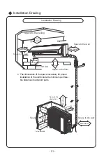
Page 23: ...Above Above Air outlet side Space to the floor The dimensions of the space necessary for proper installation of the unit include the minimum permissi ble distances to adjacent parts Space to the obstr...

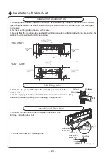
Page 24: ...UNIT 24K UNIT 694 52 194 298 256 55 55 45 82 160 14 940 Fig 5 139 184 685 157 315 70 70 36 45 65 90 Drill Piping Hole Indoor Outdoor 1 Slant the piping hole 55 70 on the wall slightly downward to the...

Page 25: ...6 3 Make the power connection cord pass through the hole at the back of indoor unit 4 Reinstall the cord anchorage and wiring cover 5 Reinstall the front panel Wiring Cover 18 24K Heat pump type N 1 2...

Page 26: ...side piping Tailing 2 Gas side piping insulation Tailing 1 Liquid side Piping insulation Fig 7 Finally wrap it with tape Water drainage pipe Left rear Right Right rear Fig 8 Fixing hook Mounting baord...

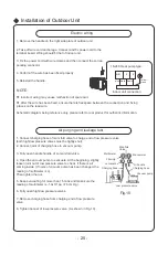
Page 27: ...authentic information Air purging and leakage test 1 Connect charging hose of mani fold valve to charge end of low pressure valve both high low pressure valves must be tightly shut Manifold 2 Connect...

Page 28: ...secure It may cause electrical leakage earth connection It may cause electric malfunction Is the power cord specified or damage the part Is the inlet and outlet been covered It may cause insufficient...

Page 29: ...r before cleaning and reinstall it after cleaning according to the ins tallation instruction Pay special attention to that silver ion filter can t be cleaned with water while active carbon photocataly...

Page 30: ...W 15 30 42000 Btu h 12306 W 12000 Btu h 3516 W 30 20 48000 Btu h 14064 W 18000 Btu h 5274 W 30 25 4 The calculation method of additional refrigerant oil and refrigerant charging amount after prolongin...

Page 31: ...mm Indoor unit throttle Outdoor unit throttle Gas pipe Cooling only cooling and heating Cooling only g m g m 6 9 5 or 12 20 15 20 6 or 9 5 16 or 19 50 15 50 12 19 or 22 2 100 30 120 16 25 4 or 31 8 17...

Reviews: