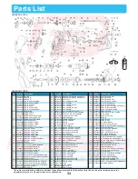
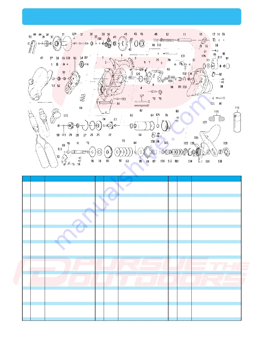
background image

34

Parts List

SEABORG 300FB

SEABORG 300FB

No,

Parts Name

Parts No,

No,

Parts Name

Parts No,

No,

Parts Name

Parts No,

There may sometimes be a difference between the purchased reel and the Dismantled Parts Chart or the parts list above due to the 

adjustment process etc. We appreciate your understanding. 

93

95

96

97

98

99

100

101

102

103

104

105

106

107

108

109

110

111

112

113

114

115

116

117

118

121

122

123

124

125

126

127

128

129

130

131

132

133

134

135

136

200

63424001

6G673001

6B962701

6F626201

6B679310

6G502001

6F366802

6F055502

6F673601

6F862901

6B747702

6F863007

6F863202

6G527501

6B862102

6F471207

6F661002

6F598405

63737813

6E134505

61608401

6X148901

6G238201

6G592701

6E096500

6B536101

6F853602

63754100

6G643501

6G659001

6G703201

6G520702

63508912

6G697101

6G701701

6G711001

6G711301

6E219701

6G430901

63737810

63754100

6Y455201

POWER LEVER NUT

POWER LEVER

POWER LEVER NUT

POWER LEVER COVER

R/S PLATE SCREW(A)

R/S PLATE SCREW(B)

HANDLE BALL BEARING WASHER(A)

HANDLE BALL BEARING

DRAG SPRING WASHER

DRAG HOLDER 

DRAG HOLDER LEAF SPRING

STAR DRAG

HANDLE COLLAR

HANDLE

HANDLE NUT

HANDLE CAP

CONNECTOR CAP

ELECTRIC POWER CORD

HANDLE BALL BEARING WASHER(B)

FRAME SCREW(B)

POWER LEVER WASHER

REEL GUARD OIL

REEL SHEET PROTECTOR

SET PLATE GEAR PIN

IDLE GEAR(B)  WASHER

R/S PLATE SCREW(B) WASHER

MECHANICAL BRAKE WASHER(C)

MOTOR GEAR(B) BALL BEARING WASHER

SPOOL GEAR PIN

MOTOR HOLDER O RING(B)

POWER LEVER O RING

FRAME SCREW(C)

CLUTCH CAM HOLD PLATE SCREW

CLUTCH CAM HOLD PLATE 

MOTOR TUBE

CLUTCH CAM LEVER BUSHING

CLUTCH CAM LEVER

R/S BALL BEARING RING

R/S BALL BEARING(CRBB)

STAR DRAG  WASHER

SPOOL GEAR BALL BEARING WASHER

OWNER'S MANUAL

1

2

3

4

5

6

7

8

9

10

11

12

13

14

15

16

17

18

20

21

22

23

24

25

26

27

28

29

31

32

33

34

35

36

37

38

39

40

41

42

43

44

45

46

47

6G696201

6F823603

6F823703

6G202701

6G526801

6F824404

6G696301

6G535201

6F211103

6G502601

6G502801

6G521301

6F859101

6F774603

6B864101

6F859401

6G099800

6G625601

6G503301

6B864101

6G696401

6G075601

6F657801

6G502501

6F274501

6B543201

6F016401

6G520801

6G696801

6G504401

6G469001

6G521001

6F550501

6G504501

6F550501

6G504601

6G281602

6G520502

6G505001

6G297002

6F766100

63754100

6G520601

6G521101

6G923401

FRAME

SPACER(R)

SPACER(L)

CLUTCH CAM BUSHING

CLUTCH CAM SPRING

CLUTCH LEVER

CLUTCH CAM

CLUTCH CAM PLATE

CLUTCH LEVER SCREW

LEVELWIND

WORM SHIELD

WORM SHAFT

WORM SHAFT BUSHING(R)

WORM SHAFT WASHER

WORM SHAFT RETAINER

LEVELWIND PAWL

LEVELWIND WASHER

LEVELWIND BUSHING

LEVELWIND POST

LEVELWIND POST RETAINER

MOTOR GEAR(A)

MOTOR GEAR(A) BUSHING

MOTOR GEAR O RING

MOTOR CASE PLATE

MOTOR CASE O RING

MOTOR CASE RING

MOTOR CASE BALL BEARING

MOTOR GEAR(B)

SPOOL

SPOOL SHAFT

SPOOL BALL BEARING(CRBB)

SPOOL SHAFT GEAR(A)

SPOOL GEAR RET(A)

SPOOL SHAFT GEAR(B)

SPOOL GEAR RET(B)

SPOOL GEAR(CRBB)

SPOOL GEAR BALL BEARING(CRBB)

SPOOL PLATE BALL BEARING(CRBB)

SPOOL PLATE

SPOOL PLATE SCREW

SPOOL SHAFT BUSHING WASHER 

SPOOL SHAFT BUSHING WASHER

SPOOL PLATE BALL BEARING(CRBB)

MOTOR GEAR BELT

IC MODULE 

48

49

50

51

52

53

54

55

56

57

58

59

60

61

62

63

64

65

66

67

68

69

70

71

72

73

74

75

76

77

78

79

80

81

82

83

84

85

86

87

88

89

90

91

92

6F853501

63749102

6G503501

6F853801

6G503601

6F252402

6G592601

6G593401

6G272301

6B864101

6G281605

6G281605

63510901

6G527701

6G520701

6G073001

6G697201

6G501801

6G173401

6F274501

6E134508

6F647201

6E351501

6G697401

6F657801

6F824901

6F211102

6F962801

6F826301

6F826201

6F938801

6F826702

6G697501

6G502402

6F796304

6F796104

6F657801

6G502901

6G697601

6G290901

6G697701

6F826101

6E335301

6G698001

6E286003

MECHANICAL BRAKE WASHER(A)

MECHANICAL BRAKE WASHER(B)

SET PLATE

IDLE GEAR(A) COLLAR

IDLE GEAR(A)

IDLE GEAR(A) SCREW

IDLE GEAR(C)

IDLE GEAR(B) COLLAR

IDLE GEAR(B)

IDLE GEAR(B) RETAINER

MOTOR GEAR(B) BALL BEARING

SPOOL SHAFT BALL BEARING

SPOOL PLATE SCREW

FINGER GUARD

FRAME SCREW(A)

MOTOR WASHER

MOTOR

MOTOR HOLDER

CORD SHIELD

MOTOR HOLDER O RING(A)

MOTOR HOLDER SCREW

DRIVE SHAFT WASHER

DRIVE SHAFT BUSHING

DRIVE SHAFT

DRAG O RING(A)

DRIVE SHAFT WASHER RET

DRIVE SHAFT RET SCREW

KICK LEVER SPRING

RATCHET

ANTI-REVERSE PAWL HOLDER

ANTI-REVERSE PAWL

DRIVE SHAFT WASHER

DRIVE GEAR

EARED WASHER

DRAG DISC WASHER

DRAG LIP WASHER

DRAG O RING(B)

DRAG COLLAR

DRAG COLLAR SHIELD

DRIVE SHAFT COLLAR

PINION GEAR

YOKE

YOKE SPRING

R/S PLATE

LINE HOLDER

pursuetheoutdoors.com/schematics

Summary of Contents for Seaborg 300FB

Page 1: ...SEABORG 300FB To take full advantage of the reels many useful functions please read this manual carefully before using Retain this manual for future reference OPERATING MANUAL Reference Reference pursuetheoutdoors com schematics ...

Page 2: ...igging master 10 Display revision Display revision Reel Specifications Reel Specification list Counter display Parts List Trouble shooting 1 1 2 2 2 2 3 3 3 4 4 4 5 6 7 8 9 17 9 10 11 12 13 14 15 16 17 32 17 18 19 20 21 22 23 24 25 26 27 28 29 30 31 33 34 35 9 10 11 12 13 14 15 16 Methods of Inputting Line The input method is simple all you have to do is just to input data for spooling the reel wi...

Page 3: ...care Dropping it may cause damage 4 Do not touch the line while reel is running It could cut your skin 5 Use this reel for fishing purposes only 6 Be careful not to get reel grease on your clothing 7 Do not use metal wire for the main line 8 Sharp impacts due to inadvertent drop or other reasons may cause reel body breakage damage to the inner electronic components and cracks or short circuit of t...

Page 4: ...e gets below DC 9 V If the display shows this when the motor is not running then battery voltage is likely to be low In this case replace the battery with a recharged one Attention 1 When changing batteries the display s backup memory stays active for about 15 minutes after the old battery is disconnected Thus the above display startup sequence does not need to replay when the new battery is conne...

Page 5: ...when washing 2 Do not use organic solvents such as benzene and thinner 3 Do not use a steel brush or abrasive cleanser 4 Do not attempt to look inside the oil hole The oil may splash and spurt out of the oil hole 1 2 3 4 4 Dry the reel well 2 Rinse detergent and dirt away with running water rinsing the spool very well to get rid of salt Use warm water under 30 degrees centigrade 3 At the fishing s...

Page 6: ...n instrument that employs electric circuity and motor Do not disassemble the reel by yourself Cover the power connector on the reel with its protection cap Old or worn cords can cause a bad connection and or short circuit Replace the cord every 2 years A B Clean and grease area A pins and area B Circumferential area Do not hang the reel by the power cord Do not wind the power cord around the reel ...

Page 7: ...nament drag Power lever Level wind One hand clutch lever Push ON clutch button Enclosed items Manual CD R Power cord Storage bag Reel seat protector Reel guard oil Levelwind threader OFF MAX ON OFF ON 1 2 3 4 5 6 7 loosen tighten weak strong pursuetheoutdoors com schematics ...

Page 8: ...king When the clutch is off simply push the button to engage the clutch to the on position If the clutch setting is OFF tilt the lever so that the clutch is set ON Names and functions of each part 1 5 4 7 2 3 Enclosed items 6 One hand clutch lever Push ON clutch button Levelwind Waterproof tournament drag Power lever Free spool adjustment Power cord Manual CD R Storage Bag Levelwind threader This ...

Page 9: ...uto stop is 2 meters Pressing this button resets the counter in the lower area of the display It memorizes distance from the bottom handy for dropping a bait right back into the strike zone after youʼve been bit The chumming timer resumes after pressing this button Once the button is pressed the INVERSE COUNTER BUTTON can not be turned off Do not continuously hold down the reset button This will p...

Page 10: ...cator time to wind up timer display 7 The chumming timer appears when motor rotation is stopped The timer display cannot be set to OFF This counter shows the depth from the bottom or a certain depth Once this counter is turned on its display cannot be turned off Winding speed can be changed within the range of 0 Hi with the mode setting display Default setting is speed 15 If the winding speed is s...

Page 11: ...and JIG PICKUP BUTTON simultaneously and hold for 6 seconds until the display shows P0 on left area of the display P0 Line Input Mode The display will change to the pickup mode 2 seconds after the buttons are pressed but keep pressing the buttons and the display will change to the line setting mode This will show the line setting display If the line is wound indoors at a low speed and with a high ...

Page 12: ... forward increases the value Pulling the lever back decreases the value 8 7 or 9 Power lever OFF MAX UP DOWN Use P0 Line Input Mode The SEABORG 300FB has data PE4 300m for the above Daiwa braided lines stored in the reel s memory Therefore when winding these lines there is no need for additional data input The table below shows the list of data Line thickness PE Display shows PE at upper left of t...

Page 13: ...eously and hold for 6 seconds until the display shows P0 on left area of the display 3 Connect the clip to the power source 12V DC MAX P0 will be blinking Levelwind Guide Main line Pin Power lever 2 5 7 8 6 P1 Inputting the line length Attention If the line is wound indoors at a low speed and with a high tension for a long period of time 1 the motor will be overheated which may cause motor failure...

Page 14: ... the OFF position after winding 11 Move the power lever to adjust line length reading in the figure on right length is adjusted to 250m 12 Press RESET BUTTON for 2 seconds and a beep will be heard The display should return to 0 0 completing the setting procedure If Err appears on the display go back to STEP 5 and re enter the data again Line data input When line length is known 10 OFF Power lever ...

Page 15: ...d with the power lever at maximum 4 Attach the cord connector to the reel See in page 2 for the connection method P2 Inputting Line Backing or 7 1 Levelwind Guide Pin Power lever 2 Main line Backing line Tie P0 will be blinking 7 While 0 0 is shown in the display press INVERSE COUNTER BUTTON and JIG PICKUP BUTTON simultaneously and hold for 6 seconds until the display shows P0 on left area of the ...

Page 16: ...ention 1 Do not wind the end of the line onto the spool because it causes incorrect length calculation Move the power lever to OFF and wind manually when nearing the end of the line 2 Braided lines less than 10 lb test can not be inputed If the line is wound indoors at a low speed and with a high tension for a long period of time 1 the motor will be overheated which may cause motor failure Tilt th...

Page 17: ...essing the buttons and the display will change to the line setting mode MODE JIG PICKUP BUTTON MODE JIG PICKUP BUTTON MODE JIG PICKUP BUTTON P3 Inputting the drawer 3 Press the MODE JIG PICKUP BUTTON and set the mode to backing line 2 P3 will be blinking 4 Paying attention to the lineʼs color coding pull 50m of line off of the spool 2 While 0 0 is shown in the display press INVERSE COUNTER BUTTON ...

Page 18: ...counter 8 Wind up the 100m of line you pulled from the reel This completes the procedure P3 Inputting the drawer If Err appears in the display go back to STEP 2 and re enter the data again Attention 1 Do not wind the end of the line onto the spool because it causes incorrect length calculation Move the power lever to OFF and wind manually when nearing the end of the line 2 Braided lines less than ...

Page 19: ...BUTTON down rapidly scrolls through the displays quickly getting you back to the depth display At each mode setting display the default setting can be retained by pressing the RESET BUTTON While letting out or winding line the MODE BUTTON cannot be used to change settings Hold down the button for two seconds to indicate the proper function from an accidental one If the MULTI BUTTON is set for jigg...

Page 20: ...N and MODE BUTTON simultaneously for 2 seconds Functionalsettingoperation 1 Mode setting display MODE BUTTON MODE BUTTON MODE BUTTON MODE BUTTON MODE BUTTON MODE BUTTON MODE BUTTON MODE BUTTON Pressing the mode button locks in the values you have set and moves on to the next display Depress and hold the MODE BUTTON to rapidly scroll back to the depth counter screen Pressing the RESET BUTTON at a s...

Page 21: ... Place the rod into the rod holder in the position it will normally rest while fishing Should your line break revise data as follows Wind the line to the rod tip and press the RESET BUTTON for 2 seconds If the display shows 0 0 then your re adjustment is complete and data has been revised Do not continuously hold down the reset button This will prevent any counter errors Functionalsettingoperation...

Page 22: ...ng at the surface Simply reset the counter to zero at the surface 3 After adjusting length press the INVERSE COUNTER BUTTON for 2 seconds When blinks this procedure is completed Default setting is 2 0 m Without pressing the RESET BUTTON the winding stops at a depth of 5 0 m The lamp will blink when the setup has been completed 4 When checking or changing a bait simply wait until the reel automatic...

Page 23: ...ounds at 2m increments above the depth of 8 m and winding stops at 2 m When auto stop depth is set the alarm sounds every 2 m above the depth of 6 m and winding stops at the set depth After auto stop stops winding the power lever can be used up to 0 0 m However above 0 0 m motor winding such as power lever cannot be employed until the RESET BUTTON is pressed Depending upon the rocking of the boat ...

Page 24: ...ction OFF 3 1 2 Once the line feeding stops due to backlash or other reasons the feeding will not start again 1 Simultaneously hold down the INVERSE COUNTER BUTTON and the MODE JIG PICKUP BUTTON to display the setting mode Then press the MODE JIG PICKUP BUTTON to display the line feeding output adjustment mode 2 Set the speed level with the power lever Default setting is zero OFF The will blinks A...

Page 25: ... m which is 6 m from the bottom 2 At the bottom move the clutch to ON by turning the reel handle or flipping the clutch lever 3 After winding up any slack line press the INVERSE COUNTER BUTTON and wind up 6 m By pressing the INVERSE COUNTER BUTTON the lower area counter is reset Wind line until the intended depth is reached Once the INVERSE COUNTER BUTTON is pressed the inverse counter can not be ...

Page 26: ...a specific fishing range has been entered into memory Display time is shown in seconds if remaining time is less than 60 seconds in minutes if remaining time is more than a minute Attention Pressing the INVERSE COUNTER BUTTON while the timer is in operation re starts the timer from 0 0 Functionalsettingoperation 6 Chumming timer Counter initially shows seconds after 1minute indicates minutes The t...

Page 27: ...a real help when dropping multiple lines T T 1 2 will be blinking OFF MAX UP DOWN 3 This displays JIG PICKUP display 3 Use the power lever to set the number of minutes Pushing the lever forward increases the minutes and pulling the lever back decreases the minutes shown is the timer set to 5 minutes 2 Press MODE BUTTON JIG PICKUP BUTTON until you come to the timer setting display 1 While 0 0 is sh...

Page 28: ...gging timing or reeling in your rig The chumming timer starts from 7 0 m on the counter unless a specific fishing range has been entered into memory Hint If the INVERSE COUNTER BUTTON and the chumming timer are simultaneously in use auto winding is possible within the period of time set for the range of 20m for which the INVERSE COUNTER BUTTON is pressed For the range beyond 20m press the INVERSE ...

Page 29: ...G PICKUP BUTTON to show the next display Pressing it also locks in the previous setting 1 3 When jigging is chosen the pickup function cannot be used Jigging pattern Jigging length Power lever MODE BUTTON MODE BUTTON MODE BUTTON MODE BUTTON 5 Jigging waiting time Jigging range 5 After pressing the MODE BUTTON JIG PICKUP BUTTON use the power lever to start jigging Jigging speed is controlled with t...

Page 30: ...h you require Pressing the JIG PICKUP BUTTON starts jigging with the display showing the indicator Pressing the button once more cease jigging The power lever controls jigging speed Shifting of jigging speed is done easily with the lever control When a fish strikes during jigging it turns off providing the power lever is turned to the OFF position After that normal winding is done with the power l...

Page 31: ... setting Preference setting Attention If jigging time is longer than the chumming timer setting then the chumming timer setting takes priority and will wind up the line Three step jigging Three step jigging Three step jigging 5 seconds interval time Interval time 5sec Interval time 5sec Example Interval time 5sec Interval time 5sec Jigging range 20 m Example Range is 20 m Functionalsettingoperatio...

Page 32: ... at the same time for 2 seconds This displays revision display Use The counter setting can be changed while fishing 1 2 3 MODE BUTTON 2 Press MODE BUTTON JIG PICKUP BUTTON to show on the display real fishing time and total winding length The figure 0 hour 0 0km indicates the amount of use This displays JIG PICKUP display Revision 1 While 0 0 is shown in the display press INVERSE COUNTER BUTTON and...

Page 33: ...ill change the reading back to the unrevised value The INVERSE COUNTER indicator will turn off once the revision has been made 4 Move the power lever to change the displayʼs reading to 100 0 Occasionally for the revision rate the exact number cannot be attained 5 OFF MAX UP DOWN 4 Setting exactly to 100 0 may be difficult If so set the display as close as possible pursuetheoutdoors com schematics ...

Page 34: ... operate the reel Disconnect the power source Connect a power source with the proper voltage Timer alarm Chumming timer winding is indicated by an alarm When recommended belt replacement timing draws near an alarm sounds and a notification message shown with the figure appears when the reel power is turned on If you see this mark please request maintenance through your sales agent with charge The ...

Page 35: ... 4 Instant max winding power power voltage 12 V smallest radius of spool Specifications may be changed without prior notice for the purpose of improvement Upper counter 0 0 999 9 m Lower counter 99 9 999 9 m 10 to 60 degrees centigrade Usable temp range Product name Product code Gear ratio manual winding Weight g oz Max Drag power kg lb Line Capacity m Instant max winding power Electric current Am...

Page 36: ...6G504401 6G469001 6G521001 6F550501 6G504501 6F550501 6G504601 6G281602 6G520502 6G505001 6G297002 6F766100 63754100 6G520601 6G521101 6G923401 FRAME SPACER R SPACER L CLUTCH CAM BUSHING CLUTCH CAM SPRING CLUTCH LEVER CLUTCH CAM CLUTCH CAM PLATE CLUTCH LEVER SCREW LEVELWIND WORM SHIELD WORM SHAFT WORM SHAFT BUSHING R WORM SHAFT WASHER WORM SHAFT RETAINER LEVELWIND PAWL LEVELWIND WASHER LEVELWIND B...

Page 37: ...Replace with a recharged battery Press RESET BUTTON to reset depth to zero with rig at the surface Adjust settings of auto stop function Reset the depth counter at the surface Connect correctly Contact your dealer if the reel does not function properly despite the above details being confirmed in the event of other problems arising and to order parts Jigging function does not respond There are cou...

Page 38: ...RMS 12851 MIDWAY PLACE CERRITOS CA 90703 U S A WARRANTY WILL EXPIRE WHEN ONE OF THE FOLLOWING HAS BEEN SURPASSED 562 802 9589 ONE YEAR FROM DATE OF ORIGINAL PURCHASE 200 TOTAL HOURS OF USE COMPANY NAME ADDRESS TEL NO pursuetheoutdoors com schematics ...

Reviews: