background image


Dake Corporation 


1809 Industrial Park Dr 


Grand Haven, MI 49417 

www.dakecorp.com


933587 


REV122022 


MAINTENANCE 


LUBRICATION 


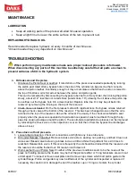
  Keep all working parts of the press well-oiled for easier operation. 

  Keep a light film of oil over the entire surface of the ram to prevent rust. 


REPLACING HYDRAULIC OIL 


Recommended to replace hydraulic oil every 6 months of machine use. 

*Amount needed may vary dependent on machine use* 


TROUBLESHOOTING 

 When performing any maintenance make sure proper lockout procedure is followed.


When disconnecting any parts of this machine be extremely careful that all parts are clean to 

prevent entrance of dirt in the hydraulic system. 


A. 

Oil leaks around the piston. 

1.  Oil above the Piston Seal or Leather: If rated stroke of the press is exceeded repeatedly by running 

the piston past rated stroke, bypass hole in the side of the cylinder run bypass line that connects 

above the piston leather. Eventually enough oil may accumulate so that when the piston is raised to 

the top of its stroke, oil is forced out between the piston and piston guide. 

This can be remedied by disconnecting the bypass tube line from the cylinder, then raising the piston 

slowly, about 2-1/2” less than it’s rated stroke (rated stroke: 18”) allowing the oil above the piston cap 

to overflow out the bypass hole into a clean bucket. Replace tube line. Oil may be put back into 

reservoir by removing the fill plug on the top of the reservoir.  

2.  Check Valve not Seated: On the first presses made with rapid advance the bypass oil was returned 

through a check valve at the bottom of the reservoir. This has been changed since so that the oil is 

returned to the top of the reservoir, above the oil level. Previously, if the check valve failed to seat 

properly when the press was operated at rapid advance speed oil was forced back through the by-

pass line causing leakage around the piston. These old-style rapid advance presses can be improved 

by relocating the check valve in the inspection cover so that the oil from the bypass line discharges 

above oil level. 


B. 

Press does not hold pressure.  

1.  Loose tube Connection: Check all connections and tighten any loose tube nuts. 

2.  Dirt under Release Valve Ball: Remove release valve stem, packing nut, packing, and ball. Clean out 

valve seat. Reseat valve ball using a brass rod as a drift and hit with significant force 2-3 times to 

reset ball. Reassemble valve. If this occurs frequently the oil should be drained from the reservoir and 

the reservoir should be flushed out. Fill reservoir with clean oil.  

3.  Worn Leather Cup or Piston Seal: If neither of the previous conditions seem to be the cause of the 

press not holding pressure the trouble may be that the piston leather or T-ring & backers are worn out 

or damaged. To inspect remove lower platen and remove cap screws which bolt piston guide to the 

cylinder flange. Piston and guide may now be lifted out of the cylinder and inspected or replaced if 

necessary. Be careful not to damage the lip of the leather cup or T-ring as it enters the cylinder. 


Summary of Contents for 33-578

Page 1: ...trial Park Dr Grand Haven MI 49417 150 TON AIR POWERED TIRE PRESS Model 33 578 INSTRUCTIONAL MANUAL WARNING Read and understand all instructions and responsibilities before operating Failure to follow...

Page 2: ...2 TABLE OF CONTENTS SAFEGUARDING THE POINT OF OPERATION 2 SPECIFICATIONS 3 SAFETY 4 SET UP 5 OPERATION 5 MAINTENANCE 6 LUBRICATION 6 REPLACING HYDRAULIC OIL 6 TROUBLESHOOTING 6 ELECTRICAL DIAGRAM Erro...

Page 3: ...ration safeguarding system The standard also discusses additional responsibilities of the employer Some of the key responsibilities are The employer is responsible for the safety use and care of the h...

Page 4: ...ght 30 Platen Diameter 25 Ram Advance Speed 1 1 2 IPM Return Speed Gravity Base 66 x 42 Height 80 Weight 3 350 lbs In the space provided record the serial number and model number of the machine This i...

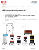
Page 5: ...d on your press safety signs Keep safety labels in good condition Replace missing or damaged safety labels Do not alter this press from its original design Do not make repairs or adjustments to any hy...

Page 6: ...all table pins are on place before applying any pressure Also make sure there is slack in the hoist cable before pressing It is advisable to lower the upper platen opposed to running the ram and lowe...

Page 7: ...the reservoir 2 Check Valve not Seated On the first presses made with rapid advance the bypass oil was returned through a check valve at the bottom of the reservoir This has been changed since so that...

Page 8: ...ocked in place with a set screw the relief valve not be tampered with after it is set to the capacity for the press D Nothing happens when pumps are operated 1 Release Valve is open Be sure release va...

Page 9: ...22 HYDRAULIC DIAGRAM Item Part No Description Qty 1 1904P Reservoir 1 2 700232 Check Valve 1 3 63453 Air Pumps 2 4 1911 Quick Exhaust Valve 1 5 710557 Release Valve 1 6 71268 Gauge 1 7 700147 Check Va...

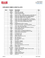
Page 10: ...4 NPT Male Bottom 1 701653 Hoist Crank Assembly W Bearing 150 Ton Consists of Items 387 Crank 606 Handle 1 84487 Label Caution Table Pins Inserted before Pressing 1 76462 Label Lockout Procedure 1 607...

Page 11: ...13 x 1 1 2 2 43373 Screw Hex Cap 3 4 10 x 2 4 24569 Screw Soc Cap 3 4 10 x 3 1 4 4 1810P Shaft Cable Pulley 1 1811P Shaft Cable Pulley 2 1819P Stop Block 4 700111 S Table Hoist Sub Assembly Also need...

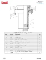
Page 12: ...9 Screw Soc Cap 1 4 20 x 2 4 6 43359 Screw Hex Cap 1 2 13 x 4 1 2 4 7 1793P Cylinder 1 8 43817 Screw Fl Hd Slot Mach 10 24 x 1 2 3 9 1871 Oil Seal 1 10 31400 Wear Ring 2 11 43358 Screw Hex Cap 1 2 13...

Page 13: ...1 2 4 7 1793P Cylinder 1 8 43817 Screw Fl Hd Slot Mach 10 24 x 1 2 3 9 1871 Oil Seal 1 10 31400 Wear Ring 2 11 43358 Screw Hex Cap 1 2 13 x 4 6 12 589 Pipe Plug 1 8 NPTF 2 13 30425P Piston Cap 1 14 4...

Page 14: ...1 Spring Valve Compressor 1 E 1095P Retainer Spring 1 F 1111 O Ring Unif 215 Buna 1 G 1096P Relief Valve Cap 1 H 43548 Screw Soc Set 10 24 x 3 4 Cup Point 1 J 1780P Valve Seat 1 701350 Relief Valve As...

Page 15: ...1752P Release Valve Block 1 B 1936 Valve Ball 1 C 1937 Washer Valve Rod Packing 8 D 1931P Packing Nut 1 E 47946P Release Valve Rod 1 F 2230A Handle Release Valve 1 G 348 Spindle Washer 1 1 2 OD x 40...

Page 16: ...haft Size 2 6 743 Gear Worm 1 7 739 Hoist Frame 1 8 742 Worm Shaft 1 9 741 Drum Shaft 1 10 745 Drum Shaft Key 5 16 x 5 16 x 4 1 11 701653 Rachet Handle Assembly 1 N A 45954 Cable 1 4 Dia 19ft 700111 S...

Page 17: ...51456 Fitting Tube 37 Deg Inch Sleeve SAE 14 2 51455 Fitting Tube 37 Deg Nut 7 8 37 Deg Flare Style B 2 1247 Fitting Tube 37 Deg Straight 3 8 x 1 4 NPTF 1 45923 Tubing 3 8 x 065 12 713339T06 Tube Ass...

Reviews: