370 S 370 S L 370 PP 370 PP L
16
feed flow control valve to stop the head just above the material.
Never have the blade adjusted closer than ½” to the
material to allow proper clearance.
5. After stopping the head, loosen the upper head setting cam. (the cam block on the bottom) Now raise this cam up to where it
just touches the limit switch without depressing the limit switch button. Securely tighten this cam down. (the power of the head
feed cylinder will actually move this limit if the cam is not securely tight)
Warning!!!!!
Never lock the cam locks half on or half off the T-slot.
6.Now adjust the lower cam block (top block) to the highest position. Then, open the head feed flow control valve and
let the head descend just past the lowest point of the material, and close the valve. Now slide the lower parameter cam setting
block (cam block on the top) down to the limit switch. Holding the cam tight activate this limit switch button. This must be
done before the head returns to the upper position. Be sure the cam is tight.
Warning!!!!!
Never make these adjustments with the blade rotating.
VISE ADJUSTMENTS
Proper vise set up and adjustments are very important for quality and safe cutting.
WARNING!!!!!
KEEP FINGERS AWAY FROM THE VISE OPENING, IT MAY CAUSE PERSONAL INJURY.
With the vise in the
open
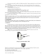
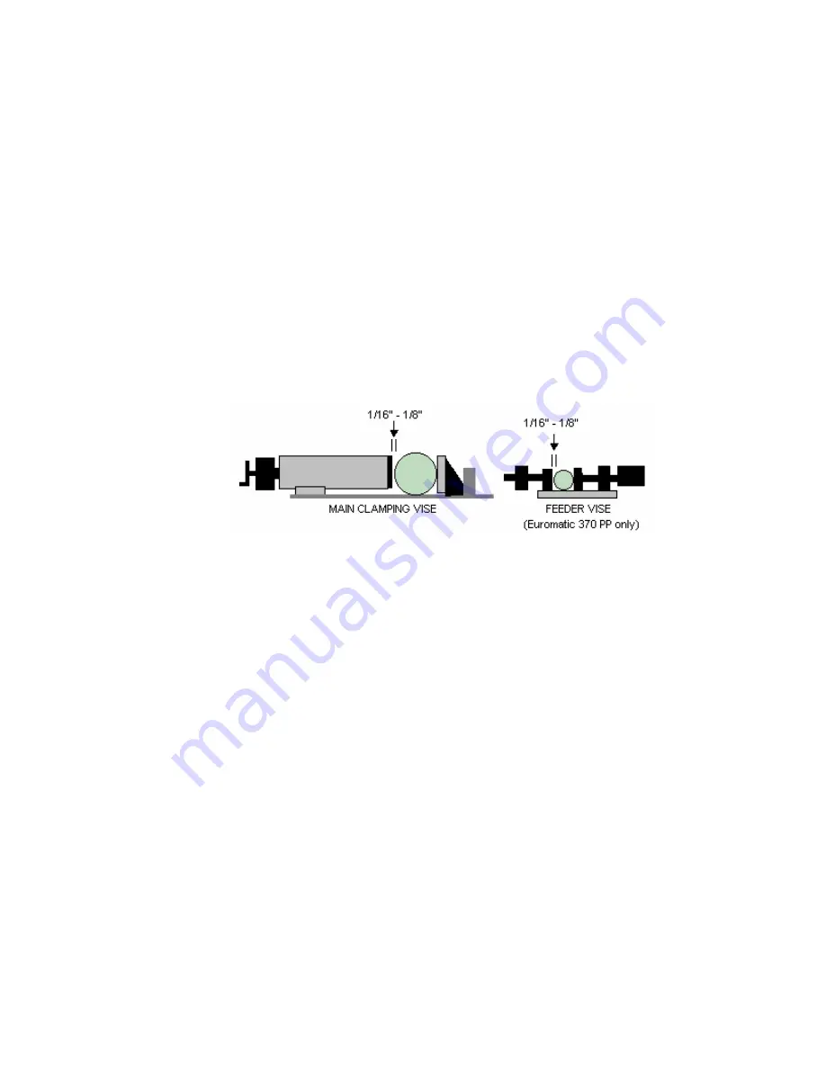
position, turn the hand wheel until you are a 1/16” to 1/8” away from the material. Push the
emergency stop button to activate the vise to see if the material is properly clamped. To deactivate the vise turn the emergency
stop button to the right.
This will be the proper setting. (Push the emergency stop button to test clamping)
Note:
The main vise can be moved left and right via T-slots. This allows you to clamp close to the blade even when making
miter cuts.
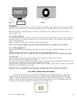
Now adjust the anti-burr arm to a setting that will clamp the material in the rear vise jaw. This is done by loosening the bolt that
holds the anti-burr arm bracket.
Note:
The anti-burr arm is not designed for clamping, but to hold the piece from moving when the blade exits the cut.
The anti-burr arm might need to be removed for some miter cutting.
For the 370 PP
machine, the feeder vise must also be adjusted. This is done to the same dimensions as the main vise.
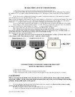
Loosen the large bolt on the rear feeder vise block, Then clamp the material in the main vise manually (Do Not use the
emergency stop button). Move rear vise feeder jaw so that it lightly touches the material (the jaw should be parallel with the
main vise). Tighten the bolt on the rear feeder vise block. Now, loosen the large bolt on the front block of the feeder vise, slide
the jaw toward the material and set as above 1/8” from the material.
Note:
The rear vise on the feeder also moves. With the material clamped in the main vise loosen the rear vise block
bolt, and adjust so the jaw is parallel with the main vise.
Note:
If vises crush the material you are cutting increase the gap in the vise dimensions.
Summary of Contents for Euromatic 370 PP
Page 9: ...370 S 370 S L 370 PP 370 PP L 9 ...
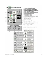
Page 10: ...370 S 370 S L 370 PP 370 PP L 10 Actual control panel layout may vari ...
Page 32: ...370 S 370 S L 370 PP 370 PP L 32 ...
Page 33: ...370 S 370 S L 370 PP 370 PP L 33 ...
Page 38: ...ALIMENTAZIONE 230V 60Hz 230V 60Hz POWER SUPPLY POWER SUPPLY ...
Page 39: ...HL4 ILLUMINAZIONE LAMA POWER SUPPLY ...
Page 40: ...LAMPEGGIATORE LAMA IN MOTO 24VAC MORSA 24VAC EMERGENCIES ...
Page 44: ...9 11 2 4 5 10 3 6 7 8 1 CH1 LC4HR424ACJ KA5 RITORNO CARRO COUNTER ...
Page 45: ...TERMINAL ...
Page 49: ...10 2 2019 Euromatic 370 2 Head Cylinder Unit Ref 005 ...
Page 51: ...10 2 2019 Euromatic 370 4 Bedplate Unit Ref 008 ...
Page 53: ...10 2 2019 Euromatic 370 6 Head Unit Ref 002 ...
Page 55: ...10 2 2019 Euromatic 370 8 Vise Unit Ref 004 ...
Page 57: ...10 2 2019 Euromatic 370 10 Group Feeder P R ...
Page 59: ...10 2 2019 Euromatic 370 12 Group Alimentador P P Ref 014b Alimentador Ref 014b ...

