- 16 -
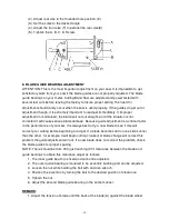
(front) lightly.
2. Be sure the nut (E) is tightened.
3. Turn the eccentric shaft(B) counterclockwise, when the bearing(D) touches the saw
blade properly, tighten the nut(E).
4. To adjust, loosen set screw(F) and move the blade adjustable up or down until it
lightly
touches the back of the blade(A).
5. Repeat 1. 2, 3, and 4 steps to adjust the other side's blade guide bearings(G).
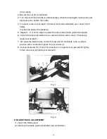
6. Correct the base and blade to be a vertical position with a scale. If necessary,
loosen set screw(F).
7. Set down the blade frame, correct the jaw vise(H) and blade to be a vertical
position with a scale then tighten the set screws (I).
8. Loosen set screw (K), move front jaw vise (J) to against rear jaw vise(H) tightly.
Finish correcting by tighting set screw(K).
Fig. 1
Fig. 2
9. BLADE TRACK ADJUSTMENT
(1). Open the blade guard.
(2). Remove the blade guide assemblies (top and bottom)
Summary of Contents for SE-712
Page 3: ... 2 ...
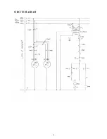
Page 22: ... 21 CIRCUIT DIAGRAM ...
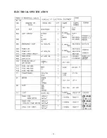
Page 23: ... 22 ELECTRICAL SPECIFICATION ...
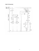
Page 24: ... 23 CIRCUIT DIAGRAM ...
Page 25: ... 24 ELECTRICAL SPECIFICATION ...
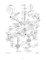
Page 26: ... 25 ...
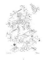
Page 27: ... 26 ...

