background image

15

INSTALLATION

Remove  the  grease  filters  before  installing 

the product, in order to avoid to damage the 

appliance.

Open the glass by rotating it as shown in fig. 

3;  then  remove  the  grease  filters  by  acting 

on their specific handle and rotate them to 

remove them from their seating (fig. 4).

Make an opening on the kitchen cabinet bot-

tom of the following sizes:

SL921 520: 500mmX270mm 

SL921 780: 760mmX270mm

Make sure the cabinet structure and the ma-

terial used allow you to make this opening 

without  causing  any  damages,  even  during 

the appliance installation.

Prepare the power supply inside the cabinet.

Prepare the air discharge hole for the pro-

duct being installed either in the sucking or 

filtering mode.

Use an air discharge pipe whose maximum 

length does not exceed 5 meters.

Limit the number of elbows in the piping, as 

each  elbow  reduces  the  air  capacity  of  the 

hood of about 1 linear meter. (Eg.: if you use 

no. 2 x 90° elbows, the length of the piping 

should not exceed 3 meters).

Avoid  abrupt  direction  changes.  Use  a 

150mm constant diameter pipe for the who-

le length. Use piping approved standards in 

force. 

Place the appliance inside the cabinet and fix 

it by inserting the screws supplied into the 

holes, as shown in fig. 5.

Both  in  the  front  and  rear  side  of  the  ap-

pliance.

Rear air outlet

Models equipped with only one motor can be 

installed having the motor air out let orien-

ted towards the appliance rear side.

If  you  choose  this  option,  you  will  need  to 

remove the motor support by removing the 

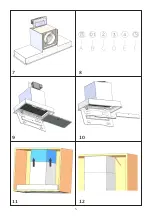
18  screws  (fig.  6),  taking  out  and  rotating 

the support, placing it in its housing , always 

keeping the air outlet oriented towards the 

appliance rear side. (fig. 7).

Secure it by using the screws previously re-

moved. 

Blocking of the stop valve

Warning!  Before  connecting  the  flexible 

exhausting pipe to the motor, make sure the 

stop valve, which is on the air outlet of the 

motor, can swing. 

Exausting version

Connect  the  flange  to  the  exhausting  hole 

with  an  appropriate  pipe.  Connect  the  ap-

pliance with the electrical mains through the 

supply cord.

Filtering version

Connect  the  flange  with  a  pipe  suitable  to 

convey the air to the top of the cabinet. Con-

nect the appliance with the electrical mains 

through the supply cord. 

Chimney installation 

Lift the internal steel chimney up to the top 

of the wall unit (fig. 11), draw with a pencil 

the rear end of the internal chimney on both 

sides (fig. 12), lower the entire chimney an-

dposi tion the fixing bracket in correspon-

den ce with the marking made (fig. 13), se-

cure the bracket with screws (fig. 14).

Lift the internal chimney up to cover the bra 

cket and secure it with screws positioned on 

both si des (fig. 15).

Summary of Contents for SL921

Page 1: ...O E MANUTENZIONE INSTALLATION USE AND MAINTENANCE INSTRUCTION IT GB INFORMAZIONI COMMERCIALI PER I CONSUMATORI COMMERCIAL INFORMATION FOR THE CONSUMER INFORMAZIONI TECNICHE TECHNICAL INFORMATION TYPE FSEC SL921 LED STRIP ENERGY LABEL ...

Page 2: ...2 ...

Page 3: ...è marcato conformemente alla Direttiva Euro pea 2012 19 EC sui rifiuti da apparecchiature elettriche ed elettroniche WEEE IT The symbol on the product or on its packaging indicates that this product may not be treated as household waste Instead it shall be handed over to the applicable collection point for the recycling of electrical and electronic equipment By ensuring this product is disposed of...

Page 4: ...4 1 2 6 3 4 5 ...

Page 5: ...7 10 8 9 5 11 12 ...

Page 6: ...13 14 15 6 ...

Page 7: ...INDICE Avvertenze Versioni d uso Installazione Funzionamento Manutenzione 7 IT ...

Page 8: ... non deve es sere convogliata in un con dotto usato per lo scarico 8 AVVERTENZE di fumi di apparecchi ali mentati con energia diversa da quella elettrica impianti di riscaldamento centraliz zati termosifoni scaldaba gni ecc Per lo scarico dell aria da evacuare rispettare le prescrizioni delle autorità competenti Prevedere un adeguata are azione del locale quando una cappa ed apparecchi alimen tati...

Page 9: ...si Particolarmente pericoloso per la sua infiammabilità è l olio già usato Non usare griglie elettriche scoperte Per evitare un possibile ri schio di incendio attenersi alle istruzioni indicate per la pulizia dei filtri antigrasso e la rimozione di eventuali depositi di grasso sull ap parecchio 9 VERSIONI D USO L apparecchio è già predisposto sia per la versione filtrante sia per la versione aspir...

Page 10: ...i come da figura 14 Alzare il camino superiore fino a raggiunge re la staffa di supporto fissta in precedenza quindi bloccare mediante le viti fornite in dotazione come da fig 15 INSTALLAZIONE Prima di procedere all installazione per evi tare danni dell apparecchio disinserire i filtri antigrasso Si dovrà procedere aprendo prima il vetro ruotandolo come da figura 3 quindi rimuo vere i filtri antig...

Page 11: ...ne della barra led si consi glia di rimuovere il listello in metallo come da figura 10 Sostituire la barra led con una di pare carat teristiche Ripristinare il listello metallico al prodotto La sostituzione del cavo alimentazione deve essere eseguita esclusivamente da personale autorizzato 11 FUNZIONAMENTO Mod SL 921 fig 8 A Interruttore on off luce B Interruttore on I velocità off motore C Interr...

Page 12: ...CONTENTS Warnings Uses Installation Working Maintenance 12 GB ...

Page 13: ... and that voltage va lues correspond to those indi cated on the label placed inside the appliance itself 13 WARNINGS Before installing the applian ce make sure that none of the parts is damaged in any way In case of damaged parts contact your retailer and do not proceed with installation Read all of the following in structions with care before installing the appliance Use an air outlet pipe of the...

Page 14: ...from the electric grid If the appliance is not provided with a non separable flexible cable and plug or with another device ensuring omnipolar discon nections from the grid with an opening distance between the contacts of at least 3 mm then such disconnecting de vices must be supplied within the fixed installation If the fixed appliance is endo wed with a supply cord and a plug the appliance has t...

Page 15: ...ig 5 Both in the front and rear side of the ap pliance Rear air outlet Models equipped with only one motor can be installed having the motor air out let orien ted towards the appliance rear side If you choose this option you will need to remove the motor support by removing the 18 screws fig 6 taking out and rotating the support placing it in its housing always keeping the air outlet oriented towa...

Page 16: ...ormance Particular care is due to the grease filter panel It can be removed by pushing its spe cial handle toward the back side of the co oker hood and turning the filter downwards so to unfasten it from its slot Fig 4 To insert the filter just perform the opposite operation After 30 hours working model the push button control panel will signal the satura tion of the grease filter by lighting all ...

Page 17: ...17 ...

Page 18: ...18 ...

Page 19: ......

Page 20: ...00000000000 05 19 ...

Reviews: