MAN#650780
BIM-12-2
Bus Interface Module for EGT and Head Temp
(Sensors are sold separately)
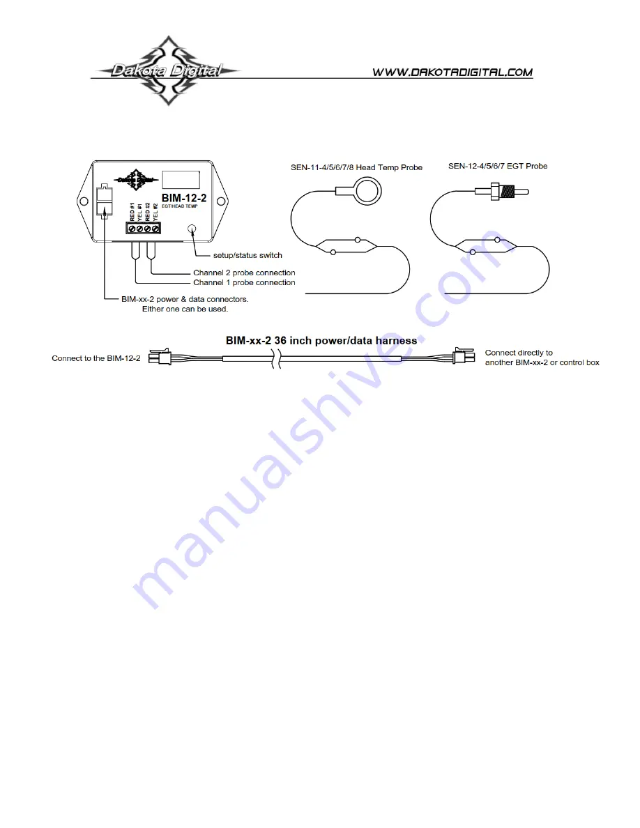
This Bus Interface Module has inputs for up to two thermocouple probe sensors, Dakota Digital part numbers SEN-11
or SEN-12. Each input can be configured individually. There are two interface (I/O) ports on the module. Either one
can be connected to the gauge system or to another module, allowing several units to be daisy chained together. Do
not connect the I/O port to anything other than a Dakota Digital gauge or BIM. Do not mount the module in the engine
compartment; it should be mounted in interior of the vehicle. The sensor harness cannot be extended with standard
wire. The sensors are available with different length harnesses. If you need a longer harness, contact Dakota Digital.
Each sensor connected to the bus needs a unique ID number assigned to it. This module has two inputs so it can use
one or two ID numbers. Each of the two inputs can be assigned an ID from 1
– 16, or turned off. The factory default
ID numbers are 11 and OFF for the two inputs respectively. The factory default labels are EGT and HEAD
respectively.
Labels available for each input are:
EGT -
Exhaust gas temperature input. This will display EGT, E, or EGT TEMP.
EGT A -
Exhaust gas temperature input. This will display EGT A, EA, or EGT TEMP A.
EGT B -
Exhaust gas temperature input. This will display EGT B, EB, or EGT TEMP B.
HEAD -
Cylinder head temperature input. This will display HEAD, HT, or HEAD TEMP.
HEAD A -
Cylinder head temperature input. This will display HEAD A, HA, or HEAD TEMP A.
HEAD B -
Cylinder head temperature input. This will display HEAD B, HB, or HEAD TEMP B.
Specs for each input are:
Sensor
resolution
high warning
HEAD -
SEN-11-4/5/6/7/8
2°F
300
– 600
EGT -
SEN-12-4/5/6/7
5°F
1140
– 1760
Temperature unit will follow the unit set for the main water temp gauge, Fahrenheit or Celsius.
Sender harness lengths:
SEN-11-4
6 feet
with ½” ring
SEN-12-4
6 feet
SEN-11-5
10 feet
with ½” ring
SEN-12-5
10 feet
SEN-11-6
14 feet
with ½” ring
SEN-12-6
14 feet
SEN-11-7
18 feet
with ½” ring
SEN-12-7
18 feet
SEN-11-8
18 feet with 14mm ring
SEN-12-9
weld-on bung


