background image

             MAN # 650702 


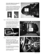
Using the 3/8” drill bit with the proper rubber 
or wood stop installed, drill a hole in the 
defrost duct in the location shown.  
 
Insert one of the four supplied grommet type 
temperature sensors into the drilled hole with 
the wires pointing to the outside of the duct 
housing.  The sensor should snap into the 
hole with the collar of the sensor resting 
against the housing. 


STEP 2:  INSTALLING THE FLOOR SENSORS 
 

Push a clip type temperature sensor onto 
the side wall of each opening of the floor 
duct so that the sensor sits inside the 
duct at about the center of the opening.  


It is recommended to label the free end of 
the sensor wires to ensure proper 
connection to the control box later. 


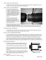
STEP 3:  INSTALLING THE CABIN SENSOR 
 

Secure one of the grommet type 
temperature sensors to the grate of the 
blower fan using the supplied 6” plastic 
ties. The sensor should be mounted so 
that the silver colored element will be in 
the incoming airflow to the fan when the 
fan is running.  


Be careful that the plastic tie, the sensor, 
or its wires will not contact the fan blades 
when the fan is running.  


Label the wires for the Cabin Sensor for 
easier identification later. 


Defrost 
sensor 
location 

Floor 
sensor 
locations 

Summary of Contents for DCC-4000

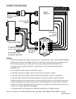
Page 1: ...H THIS SYSTEM DCC 4000 display x1 DCC control box x1 HLC harness x1 11 plastic ties x6 6 plastic ties x2 Grommet temp sensors x4 Clip temp sensors x2 DCC controller harness x1 DCC display harness x1 Mount brackets x2 Thumb nuts x2 Installation operator s manual x1 Cutout template x1 2 Vent sensor housings x2 2 Vent sensor housings x2 ...

Page 2: ...tor to the 12 pin connector on the GEN IV module Connect the 16 pin wire connector to the 16 pin main wiring harness connector on the GEN IV Connect the GEN IV harness into the remaining 16 pin connector on the DCC controller harness optional Using the HLC harness 2 six pin connectors connect to either one of the 6 pin connectors on the DCC 4000 display Connect the other end to the CLOCK CABLE por...

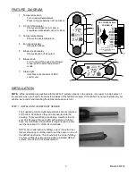
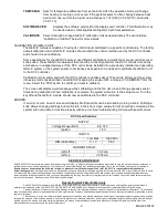
Page 3: ...commend installing the temperature sensors first STEP 1 INSTALLING THE DEFROST SENSOR The supplied grommet type temperature sensors require a 3 8 hole to be drilled so they can be inserted into the housing To prevent drilling too deeply create a stop for your drill bit see photos at right with a piece of rubber hose or small block of wood that is long enough to allow just the tip about of the bit ...

Page 4: ...uct so that the sensor sits inside the duct at about the center of the opening It is recommended to label the free end of the sensor wires to ensure proper connection to the control box later STEP 3 INSTALLING THE CABIN SENSOR Secure one of the grommet type temperature sensors to the grate of the blower fan using the supplied 6 plastic ties The sensor should be mounted so that the silver colored e...

Page 5: ...lled There are two tabs on the case of the control box to allow for easier mounting STEP 7 WIRE THE TEMPERATURE SENSORS Wire the temperature sensors wires to the connection strip on the DCC control box The small tab on the top of the connector can be pressed down with a screw driver to allow insertion of the stripped ends of the sensor wires Connect the black wire to the terminal The other wire is...

Page 6: ...s under automatic control AUTO will appear in the fan speed display area Making adjustments to the fan speed will take the fan out of auto mode and the AUTO will no longer be displayed Automatic fan speed can be turned back on by turning the knob past the maximum setting The fan will also return to auto mode whenever an adjustment is made to the temperature setting TEMPERATURE KNOB knob on left si...

Page 7: ...he AC econ mode If the system is currently in AC mode it will turn the AC off If it is currently in econ mode it will turn the AC on AC mode is indicated by a snow flake next to the temperature reading Econ mode is indicated by a backslash circle over the top of the snow flake There are instances when the AC Econ mode may not be overridden Two of these instances are the full cool 60F setting and t...

Page 8: ...tem settings DAY NIGHT Sets the same theme for both day and night modes DAY MODE Sets just the day mode theme and leaves the night mode theme unchanged NIGHT MODE Sets just the night mode theme and leaves the day mode theme unchanged Each option above has the same set of preset themes to choose from plus two additional options listed below CUSTOM THEME This is a user customizable theme On selectin...

Page 9: ... help with specific errors DCC Specifications SUPPLY Voltage Range BAT 8 to 18 V Ignition 5 V INPUTS Low Max High Min DIM dash lamp 3 1 V 3 8 V CURRENT DRAW IGN off 0 2 mA IGN on 200 mA SERVICE AND REPAIR DAKOTA DIGITAL offers complete service and repair of its product line In addition technical consultation is available to help you work through any questions or problems you may be having installi...

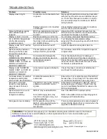
Page 10: ...splay reads OPEN CABIN VENT A VENT B FLOOR A FLOOR B DEFROST SENSOR Listed sensor appears disconnected Check the connection of the sensor wires for the sensor listed Also check the sensor wires for breaks or pinched areas Display reads SHORTED CABIN VENT A VENT B FLOOR A FLOOR B DEFROST SENSOR Listed sensor appears shorted to ground Check for proper connection of listed sensor and check for pinche...

Reviews: