5
MAN # 650702
STEP 4: INSTALL THE GEN-IV MODULE
Install the GEN-IV module if it has not yet been installed in the vehicle. Refer to the installation manual for
the GEN-IV module for detailed instructions for your application.
STEP 5: INSTALL THE VENT SENSORS
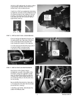
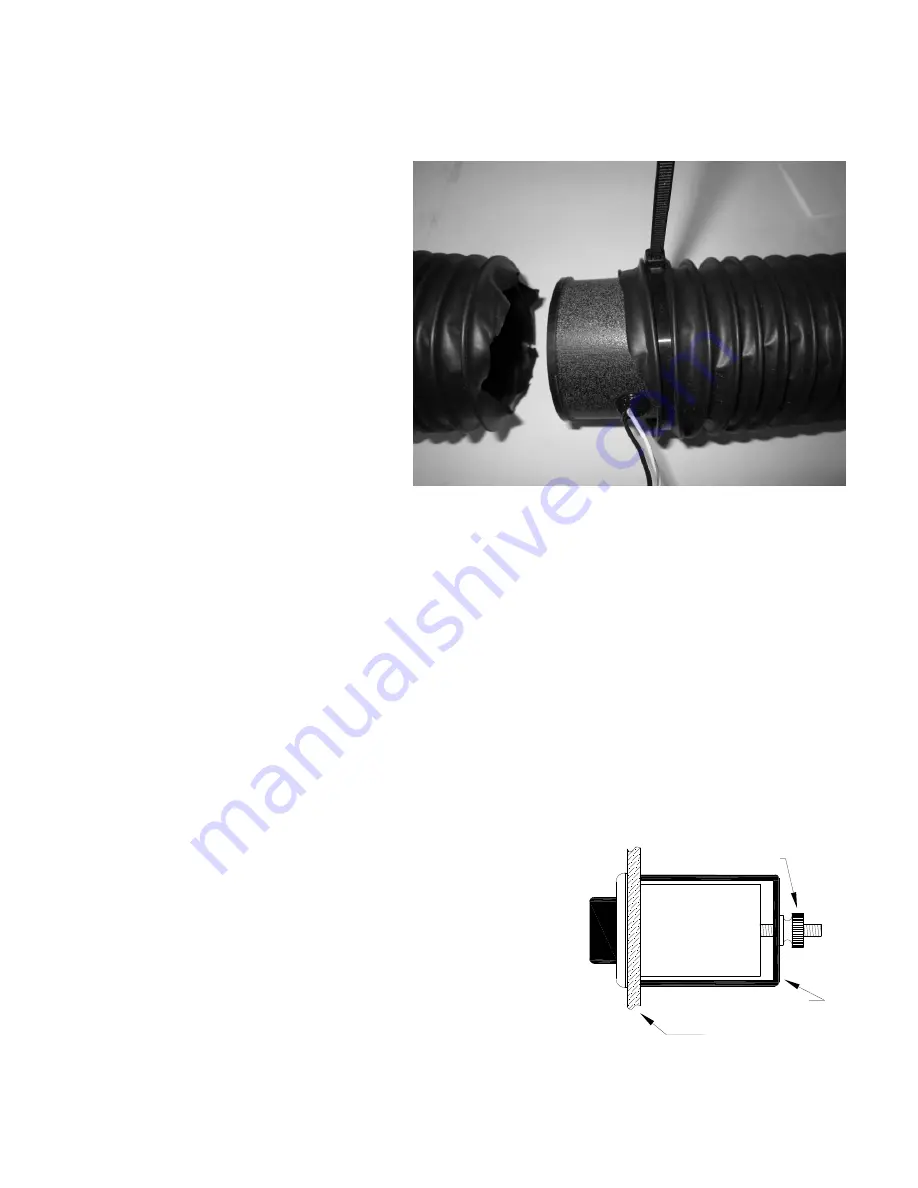
The vent temperature sensors are
mounted in the flexible duct tubing from
the GEN-IV module. Determine which
two tubes will have the sensor and cut
the tubing a minimum of 6” away from
the GEN-IV module. Choose tubes to
vents that will blow the most air or blow
most directly on passengers in the
vehicle.
Of the four included Vent Sensor
Housings, use the two that fit the
diameter of the cut flexible tubing. Insert
the two remaining grommet type
temperature sensors into the predrilled
holes in these Housings.
Work the Vent Tubes over both ends of
the Sensor Housing and secure the tube
on both sides of the housing using the provided 11” plastic ties. Make sure the plastic ties are positioned
over the body of the Sensor Housing so the raised end of the Housing holds the Tube from slipping off.
STEP 6: MOUNT THE CONTROL BOX
Find a location to mount the DCC control box where the wires will reach without being pulled. There are
two tabs on the case of the control box to allow for easier mounting.
STEP 7: WIRE THE TEMPERATURE SENSORS
Wire the temperature sensors’ wires to the connection strip on the DCC control box. The small tab on the
top of the connector can be pressed down with a screw driver to allow insertion of the stripped ends of the
sensor wires. Connect the black wire to the “-” terminal. The other wire is connected to the “+” terminal.
Take care when connecting the sensors to the control box. If the sensors are connected to the wrong
terminals, the controller will not control the temperature properly. Either Floor Sensor can be connected to
either of FLOOR terminal (A & B). Similarly, either Vent Sensor may be connected to either VENT terminal.
STEP 8: MOUNT THE DISPLAY
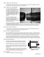
Determine your mounting location of the display and use the
provided cutout template to make the opening for the display.
Insert the display into the opening from the front of the dash.
Place a mounting bracket onto each of the studs so that the two
legs of the bracket contact the dash panel along the sides of the
display unit.
Place a thumb nut onto each of the studs to hold the bracket in
place. Tighten the thumb nut to push the bracket up against the
back of the dash panel to secure the display in place.
STEP 9: WIRING
(Refer to the wiring diagram and steps on page 2.)
dashboard
Mounting clip (x2)
thumbnut (x2)


